
Ever seen the little lightning bolt next to an AutoCAD block and wondered how to make these magical adaptive blocks? The Block Editor can be a scary place, but in this blog I will attempt to make it that little bit less intimidating. At the end we will be able to set free the creative block making genius inside of you.
Dynamic Blocks
Before we get started, a quick introduction to Dynamic Blocks. Blocks in general allow us to quickly replicate repetitive geometry in our drawings, treating them as one unit. This allows us to move, rotate and scale all the individual lines, arcs, and circles (and any other lovely geometry) we have placed as detail in an item, as one solid object. Where dynamic blocks go a step further, rather than our block being a static version of itself, we can have varying iterations, visibility, and sizes of the same object. So rather than having a different block for separate configurations, we can have one block containing all versions of an object.
Editing your Block
Once we have created our block, we can begin to edit it, depending on the block this will take either a double click on the block in your drawing or a single click to select it, then selecting Edit in the Block panel. Both options will take you to the Edit Block Definition window.
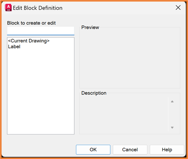
From here you select the block you want to edit, if not already selected, and click OK.
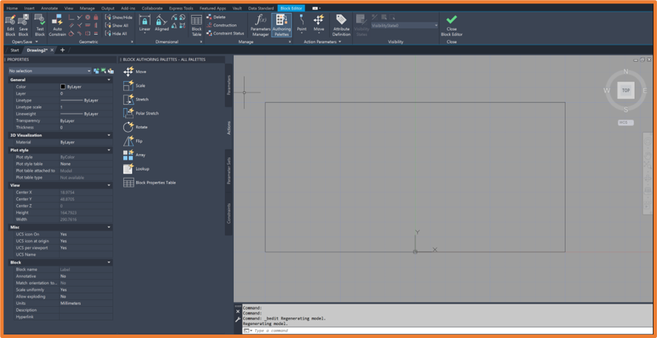
This will take us into the Block Editor. Just bringing your block here does not make it a dynamic block automatically. We will need to add some intelligence to the block from here, but you can make other geometry edits to your block from this view if needed. Notice the grey background that indicates we are in a separate environment.
Dynamic Controls
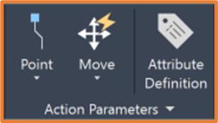
The dynamic tools are separated into two main categories, Parameters and Actions. These are interlinked, as a Parameter needs an Action, and an Action needs a Parameter. We can use a single parameter for multiple actions. These controls can be found either in the Action Parameters Panel, in their respective Parameters and Actions dropdowns.
Or in the Manage Panel > Authoring Palettes.
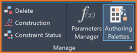
The Authoring Palettes will have the Parameters and Actions in their own tab along the side, as well as Parameter Sets and Constraints.
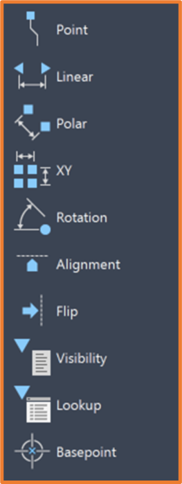
Parameters
These will be the input we give when editing the block and will show once the block is selected as grips. Parameters control the amount, direction, and selection of the changes we want to make to our block.
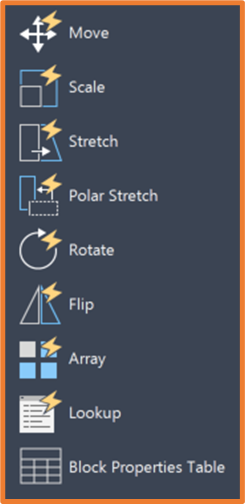
Actions
These are what we will use to enforce which geometry is adjusted when we change a parameter. Whether it be a single object, or multiple, and this will also drive how the item moves, whether it be as Stretch, Scale, Move, Rotate, etc.
Creating a simple Dynamic Block
Stretching a block
Starting with a simple rectangular block, we would need to add a Parameter first, in this case a Linear Parameter which will allow us to set a linear value for movement required.
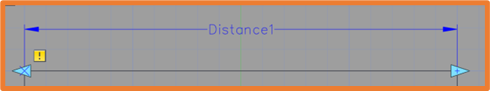
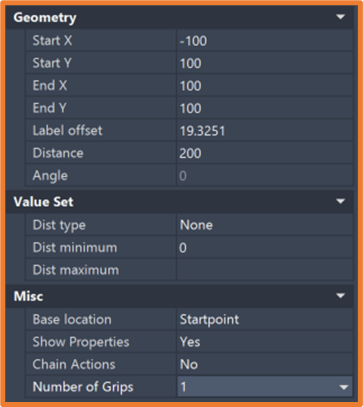
This will need to be placed on the two extents of the block to give the default value of the distance between the two points. If you have your properties palette active, and select the Parameter, you will notice under the Geometry section you have a Distance value. We also have controls on the Number of Grips, and Base Location. These will set whether you can change the value in one, or two directions, and which direction or point is set as the base. In this case I only want my block to stretch in one direction so I will set Number of Grips to 1.
Once the Parameter has been added, I will need an Action.
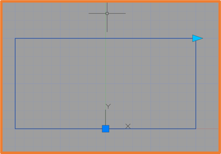
Because we want to adjust the size of the block but only in one direction, we want to use a Stretch action. This will ask for a parameter to link, I will choose the Linear Parameter from the last step as my reference. It then needs the point to use as reference, we will use the only point on that parameter which is now displayed as an arrow.
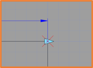
We then need to specify the geometry, in this case selecting an area that won’t be affected by the stretch and will move all items in the field as one object, while it will stretch any necessary objects outside of the field. I will draw a box around the vertical line I want moving as part of this action. In this example the geometry is below the Parameter arrow we used for the Action.
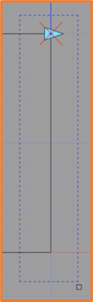
The last selection AutoCAD needs is for us to define the objects that will be affected by the stretch, in this case any item that will be moved or stretched. Since we have a simple rectangle in this example, I we’ll select all geometry. Then hit enter once we are happy with your selection.
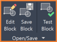
This should now be finished, and we can test the behaviour of our block. In the open/save panel, we have a Test Block option which takes us into the test environment, you could save this block and test it in your drawing if needed. I will enter the Test Block environment.
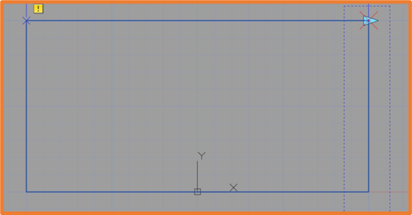
With the block selected, we should now see the Arrow Grip of the Parameter. Clicking on it and moving will now stretch the block using the action we added. Note how distance value changes as we drag this grip.
If this is your first time making a dynamic block, congratulations! You have just completed and tested your first block. Hopefully that was easier than you expected.
Take a moment to enjoy the automation of your design.
Rotating a Block
For the next example, we want to ensure our block can rotate. We will use the same block, but for simplicity, remove the stretch option in this example.
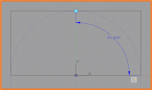
This will require the Rotation Parameter to drive the angle of rotation. This needs a basepoint, which will be the pivot point of rotation. I will choose the basepoint of my block, but this will depend on the nature of your block. You will then be asked to specify the Radius, which will define the offset of the grip from the base point. It will then ask for the Default Rotation Angle, this will set the default position of the grip at an angle from the basepoint. We will then choose a placement position for the Parameter.
Next, we will add the Action. For this we will add Rotate (shocking I know!). This will require a Parameter, where we can select the Rotation Parameter, and for Objects, we can select everything.
Once this is selected, we can test the block once more.
Creating a form
In this final example we will create varying sizes of the same object. This one takes a few extra steps to ensure the object keeps within the design intent.
The first step for this will be adding Constraints, these ensure that the objects move in a predefined way. We can ensure items remain Vertical, Horizontal, are always attached to each other using Coincident, or Parallel/Perpendicular to each other, as well as a few other options.
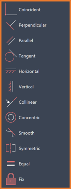
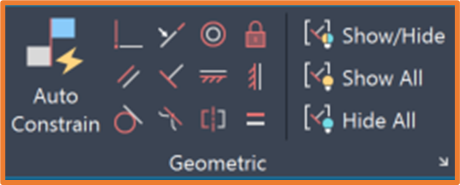
These can be found in the Constraints Tab of the Authoring Palettes, or within the Geometric Panel on the Ribbon.
For this example, we want to ensure our Rectangle is always a Rectangle, and therefore always has four 90-degree corners. To force this we will need to ensure each corner has Perpendicular constraints between the connected lines.
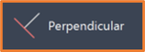
Adding this is as simple as selecting Perpendicular from the list.
And applying this relationship between the two connected lines in the corner. We can repeat this for each corner.
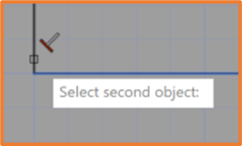
Notice that on the fourth corner you get an error stating the action would Over-Constrain the object, this is because we have three 90-degree angles already, which will force the last corner to remain at 90-degrees anyway. We can cancel this box and accept that we only need Three Perpendicular Constraints.
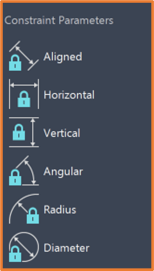
Once constrained, we need to define the dimensions of the object, we therefore need to add Constraint Parameters or Dimensional Constraints. These will drive the length or angle of a line, or Radius/Diameter of an Arc or Circle.
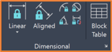
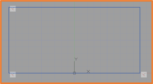
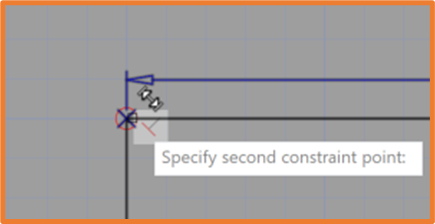
Adding an aligned dimension to the endpoints of a single Vertical and a single Horizontal line will drive the length of these lines respectively. Since we have added constraints keeping the lines perpendicular, this will also drive the Height and Width of the rectangle.
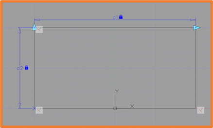
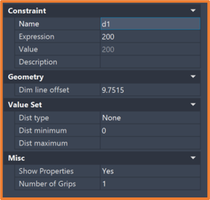
Once these have been added in, we can rename each of the dimensions in the Properties palette to Width and Height respectively. This will ensure better visibility on each dimension and gives a quick description of the value it changes. However, this is not a necessity.
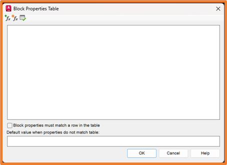
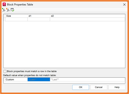
Now that the Dimensions are set up, we want to set a table of values for these. This will again require an action, this time in the form of a Block Properties Table. Which will need to be placed on the block in a position you want to make the edits from. Usually near the Basepoint.
This will open the below window, where we can add Properties, which will take us to a list of Existing Dimensional Parameters, or add new User Parameters.
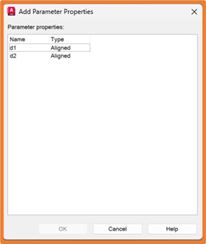
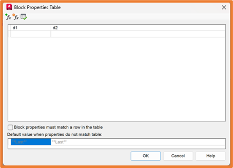
Selecting Add Parameter Properties will give us a list of all the dimensions we have added into our block, in this case d1 (Width) and d2 (Height). We want to add both by double clicking on them individually.
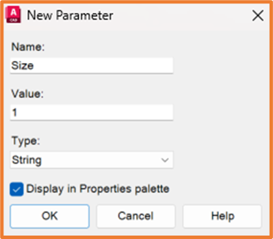
Once added to our Properties Table, we can add a name for each configuration. To do this we need a new property.
We will add one called Size, but this can be called anything you want. Setting the Type to String will allow us to put any text in the new Size field.
We can drag the Size column to the left and reorder any other columns we may want to adjust.
We can now start to fill out our table. The first column in the table (size in our example), is the option that will be displayed in a list for users to choose from. These size values can either be the actual dimensions of the configuration, the part number, or any other naming convention you want.
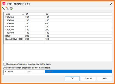
The values that do the work are the ones in each Dimension column. For 200 x 100 we have set a value for d1 (Width) of 200, and d2 (Height) of 100.
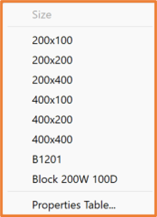
Once we are happy with our list, we can close the table and test our block.
Where we will now see the name of the property used for choosing the sizes (size) and a list of values for the property. From here we can choose a value in the list and should see our block change sizes according to the table we created.
If you find that your block is adjusting around your basepoint, you could add a vertical and horizontal constraint between the basepoint and the vertical and horizontal lines.
For more information, check out our video where we look at this further: Dynamic Blocks in Autodesk AutoCAD – YouTube
Still got Questions?
Book Training
With our range of AutoCAD courses we can teach you best-in-class 2D and 3D design skills. This includes drawing, taking measurements, producing templates and everything required to create your designs.
Contact Us
We are here to ensure you receive a consistently high service and quality solutions for your business needs. We promise you won’t regret speaking to us, and if we can’t help you, we will try to find someone that can.