
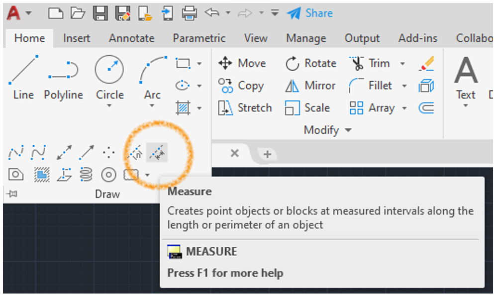
The AutoCAD Measure command doesn’t actually measure something as you’d expect from the command name, instead it allows us to create points along an entity at set intervals along the entity length, each point can be represented by a node or a defined block.
The command can be found on the Ribbon on the Home tab, then Draw panel, we can also just type the command….MEASURE.
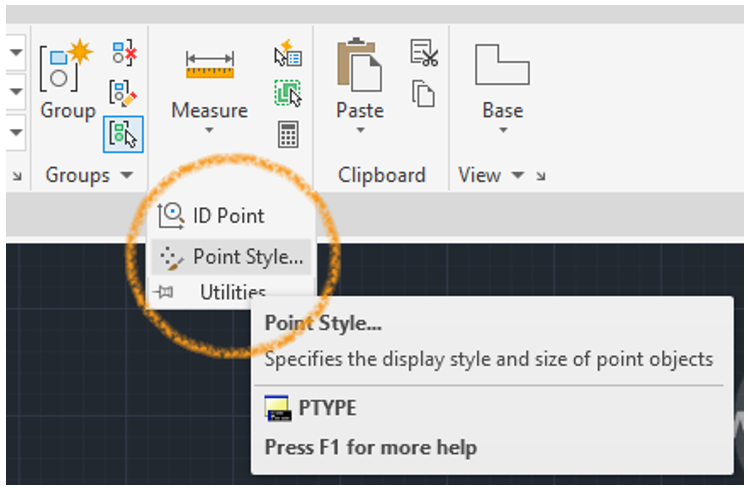
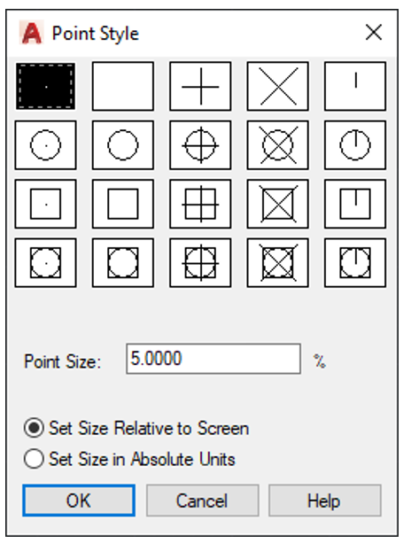
Nodes are defined separately using the Point Style by either typing PTYPE then choosing from the dialogue our preferred Point Style, or from our Home tab followed by the Utilities panel and Point Style (depending on how our version of AutoCAD is configured). We can choose a style of node to display and the size of it with a percentage figure relative to the screen view or by chosen units. (Sometimes if your nodes don’t display correctly it’s usually because they are set to absolute units and are too small on your screen to see).
Real World Application
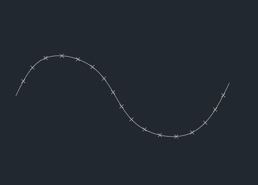
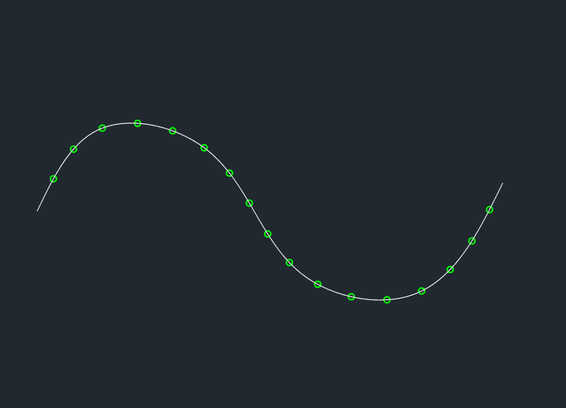
If we take a Polyline and we think about it as a length of fence approximately 240m long and we want to add a post at equal points we would invoke the Measure command selecting our object, the Polyline in this case, then type length and then specify the length of each segment along the Polyline, for this example we’ll specify 20m.
AutoCAD then places a node along our object every 20m depending on our chosen Point Style in our example a cross style.
One thing to note here is that the object we want to use the Measure command on has to be a continuous object like a Polyline or a Spline, and not a series of single lines and\or arcs making up the complete length.
Adding the Fence Posts
Now we want to add our fence posts at each 20m segment we could if we wanted simply just copy a circle to represent the post to each node point using a node snap, which is fine but along a really long fence? This is where instead of adding a node point at each 20m segment we can insert a defined block for each fence post position. When defining our block for our post we need to remember where the block insertion point will be, so in our example the fence post centre will be our block insertion point. Here we’ve created a block called post to represent each fence post position. This time invoking the Measure command, we again select our object (the Polyline) but this time instead of our 20m segment length we now type block and then enter our block name, in our example being post. AutoCAD then asks if we want to Align block with object? We’ll stick with the default for now of no….We’ll use this in our next example….We can now as we did before enter our segment length of 20m. We now get our defined block being our green fence post at every 20m along our chosen object.
Fence Post Orientation
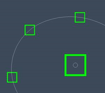
So what if we wanted a square fence post instead of a round one at each point? We can insert anything as a block at each of our 20m segments, here we’ve added a square post but you’ll notice the post remains in the same orientation along our length, with the insertion point of each block again being the middle of our post……The circle in the enlarged view of the block.
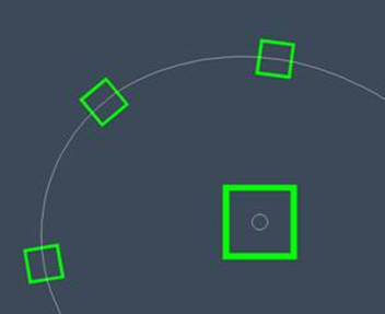
We can align our block along the length of our object, so doing the same as before we invoke the Measure command we again select our object (the Polyline), we now type block and then enter our block name, AutoCAD then asks if we want to Align block with object? Here we say yes and enter our 20m segment length again, AutoCAD then inserts our block at the defined 20m segments, but this time rotating our block with our object as it goes. So now we have our square fence posts every 20m along our fence line.
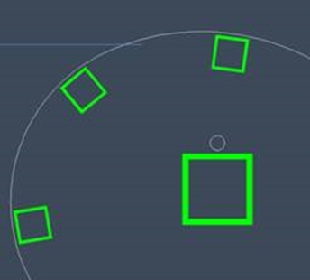
So now we have our square fence posts every 20m along our fence line, if we want to have our posts ‘within’ our fence line we simply redefine our post block with the insertion point to push the post inwards from the path of the fence.
There is a similar command called Divide but this actually does what the command suggests, it divides your chosen object equally. So in our example if we entered 20 it would divide our object into 20 equal segments, rather than adding something every 20m along the length. Using Divide we can also add a chosen defined block, again only at each 20th of our divided object, and not at every 20m.
I’ve used both Measure and Divide for all sorts of things, lamp post positions along a road, fence posts, tree positions, pile positions along a harbour wall, mile markers along a tidal estuary, chainage lines through a river canoe pass……..Anything that needs a measured division point, along with the handy insertion of a defined block.
Still got Questions?
Book Training
With our range of AutoCAD courses we can teach you best-in-class 2D and 3D design skills. This includes drawing, taking measurements, producing templates and everything required to create your designs.
Contact Us
We are here to ensure you receive a consistently high service and quality solutions for your business needs. We promise you won’t regret speaking to us, and if we can’t help you, we will try to find someone that can.