
The likelihood is that if you are reading this blog, you have an Autodesk Product Design and Manufacturing collection and would like to understand how to get a quick render out of 3ds Max using your Inventor data and the Arnold render engine. Whilst 3ds Max is an intensive and in depth application, good results can be achieved relatively quickly these days, and hopefully the steps in this short blog will help get you started.
We will start inside of Autodesk Inventor, with an appropriate model that we would like to create a render of. For the purpose of this blog post, we have used the standard Autodesk Inventor Professional 2020 hero model.
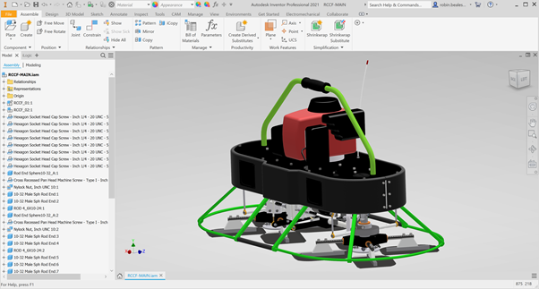
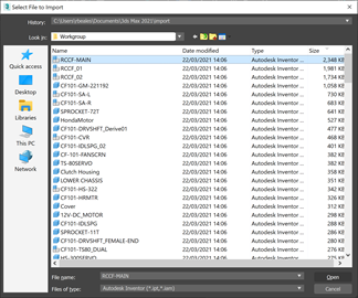
Alongside Autodesk Inventor, open 3ds max and select File > Import > Import before browsing to and selecting your Inventor file. In this case, we choose the top level assembly for our design.
3ds Max will load up our design in the background before displaying us with several import options. For this step by step guide the selected options don’t matter too much so we will leave them on their default settings.
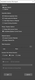
After clicking on OK, 3ds Max will start the import process using the Inventor data selected. Depending on the complexity or size of the imported model this process may take anywhere from a few seconds to several minutes. A progress bar will be visible at the lower left of the screen.

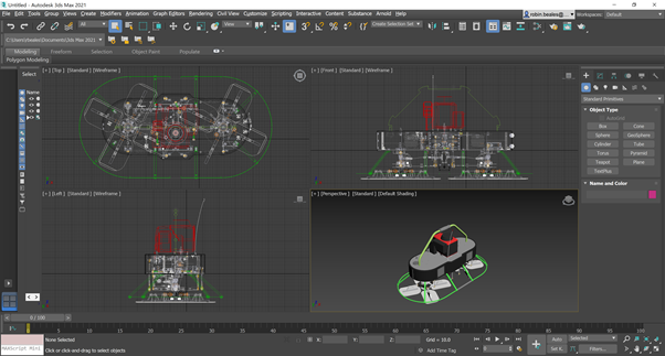
The import will complete and your model will be displayed inside of 3ds Max. You will notice the similarities between the models appearance as well as the look and feel from Inventor. Both Autodesk Inventor and 3ds Max share the same “Autodesk Material Library” to make this process work, and the same is true from AutoCAD, Revit and other Autodesk applications.
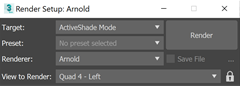
The first thing we are going to do is create a simple studio ramp alongside some lighting for our scene. Before doing so, head over into Render Setup and ensure that you have chosen “Arnold” as your render engine, using either “Active Shade” or “Production” mode depending on your hardware spec or preference. I am using Active Shade for this example.
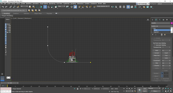
Head over into a left side view, I have used ALT+W to enter a maximised single viewport before pressing L to enter the left view. Once there, draw a line to match the following output. I have used 3 points before filleting the corner to give a smoother ramp shape.
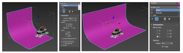
From here head into a perspective view by hitting P on your keyboard and orbit your view using CTRL + R, pan using your middle mouse and zoom using your mouse wheel to move to a more appropriate view. With the line still selected, choose the extrude modifier to extrude a 3D surface using your line. Specify a value that makes sense with the size of model you have. Next select the mirror modifier to mirror the object through the Z axis as a copy.
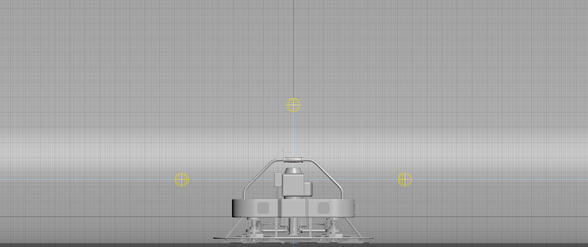
Use your front view by pressing F on the keyboard to place some Arnold lights in the positions highlighted below. We use Arnold lights as we want to use the Arnold render engine. Once you have placed your lights, check their position using the top view (T). Your lights should be centred around your model.
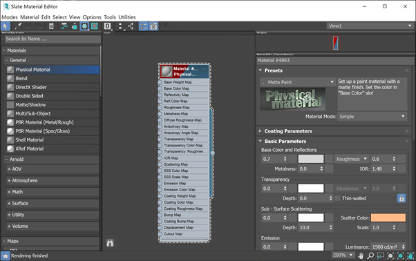
Now before we run our first test render, which will likely need some tweaking to the lights as well as the scenes exposure control, we want to set the materials to something that will suit Arnold better than the default Autodesk materials. To start with, we will set all objects to the same material by opening up the material editor by pressing M on the keyboard before dragging and dropping a Physical Material into the editor and choosing a matte paint template, before selecting an off white colour. Assign this new material to our ramp and Inventor objects by using “Assign Material to Selection” .
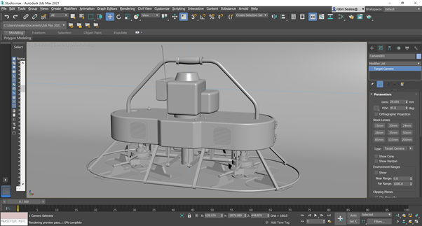
We could at this point render the scene or start active shade, but it would be beneficial to have a camera created to focus in on your product and give us a little more control over the output. Use a mixture of views to create a target camera looking at your product before activating this camera using C on your keyboard.
Your final step before getting any meaningful results is to enable some expose control for your render. Select either Rendering > Environment or press 8 on your keyboard select Physical Camera Exposure Control before choosing render preview. Use this preview to tweak your exposure control to suit. If your render is still very dark, move your lighting closer to your product and adjust up both the intensity and exposure on your lights – remember that small steps are key here and try not to make large jumps.
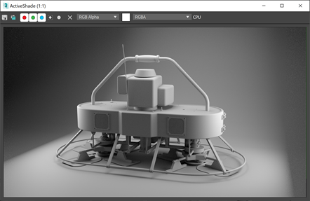
Once you are happy with the look of your output open your render settings and choose a more suitable output size before choosing to render. In my case I am using Active Shade and an output size of 1920 x 1080, which took 30 seconds to a minute to create this output on my machine (Intel i7 10850H @ 2.7GHz, 64GB RAM, Quadro RTX 4000)
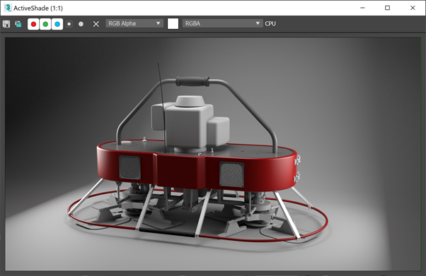
To finalise your render, you can add additional materials as well as boosting the Arnold settings in order to achieve a greater quality output. The following example uses the default Arnold output settings, again from an active shade render of the same time. The only difference is using slightly more materials, again from the standard Physical Material template but with slightly different settings. As a side note, as soon as you start using materials with textures you will need to assign UVW map as a modifier to each component with a texture in order to display the object correctly.
Still got Questions?
Book Training
Our range of Autodesk Inventor training courses will teach you how to create production-ready parts and assemblies through hands-on learning experience. Make sure you contact us to find out which course is best for you.
Contact Us
We are here to ensure you receive a consistently high service and quality solutions for your business needs. We promise you won’t regret speaking to us, and if we can’t help you, we will try to find someone that can.