The Product Design extension within Autodesk Fusion 360 is a great addition to the Design workspace. This allows us to create rules for materials we work with. These rules can include a Thickness range, Draft angles, Nominal radius and more. Giving us great intelligence in the design process, which helps automate the process further.
Plastic Environment
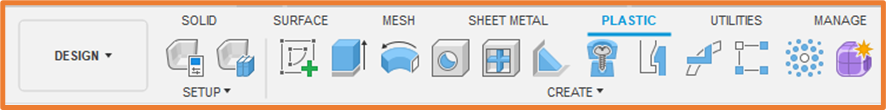
The plastic environment is in the Design Workspace within Fusion 360 and will require the Product Design Extension to access the core tools. Extensions are paid for additional functionality in Fusion 360 which give you access to more tools than you get inside of base Fusion.
Plastic Rules
Using Plastic Rules in the Product Design extension allows us to choose modelling parameters which will guide the design as we apply features. These are assigned to components in your design.
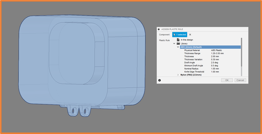
Fusion comes with various pre-set rules built in, these rules can be edited and created within the Plastic Rule library.
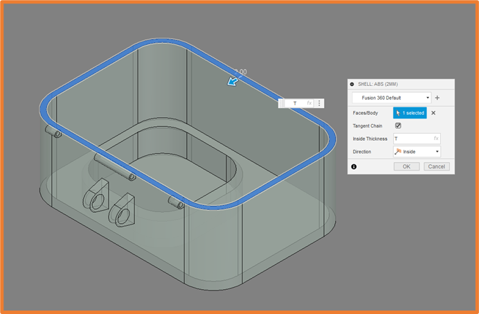
The rules will then be used when adding features to your component.
Shelling your component will take into consideration the Thickness defined by the rules.
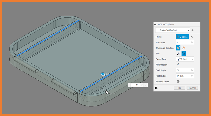
Webs and Ribs will take the Thickness and Draft Angles into consideration.
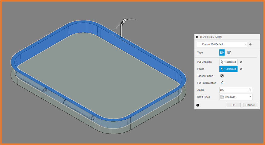
Drafts will understandably be driven by the Draft Angle
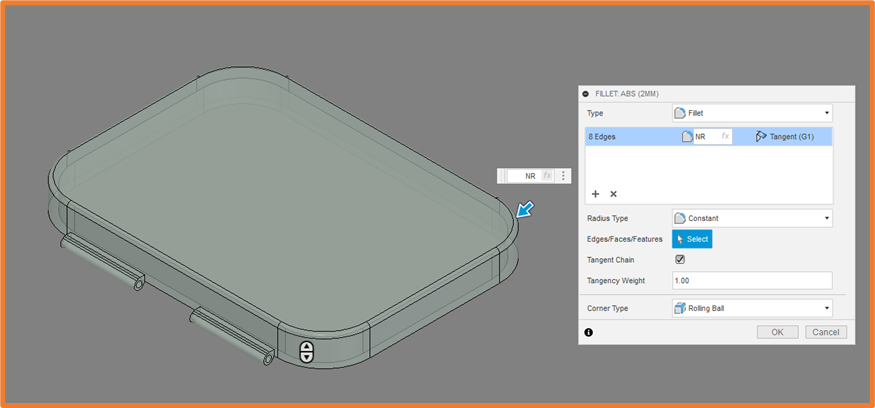
Fillets will grab the Nominal Radius value to name a few.
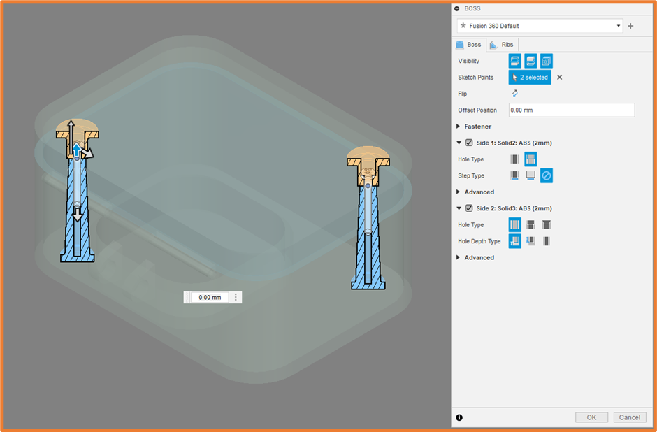
Boss
This is a great tool within the Design Extension, allowing us to create bosses inside of our component, driven by sketch points. This will require a sketch with points to drive the positioning of the feature.
This will automatically merge the sketch plane, to the next surface with a boss. The boss will take the Draft Angle and Thickness into account.
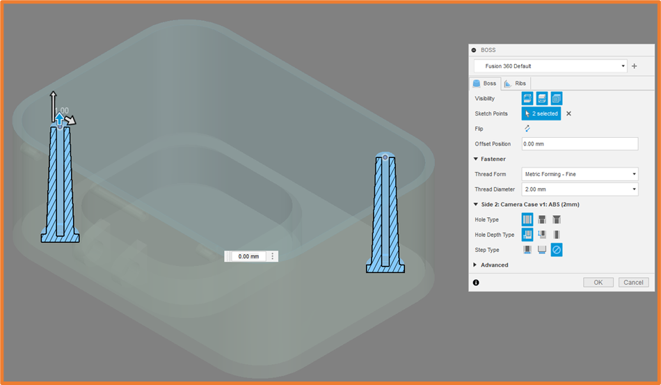
If you enable the visibility of two connected bodies, it will automatically create two boss’s one on either side of the sketch plane connecting the two parts. We can also insert Fasteners and configure their type and size within the dialogue.
Snap Fits
Similar to Boss’s, Snap Fit’s are driven in their positioning by sketch points. These create geometry on bodies in one of three types (Parallel Hood and Groove, Perpendicular Hook and Groove, as well as Hook and Loop)
These features will again be driven by the plastic rules set out for the part, picking up the Thickness and Draft Angle. You can adjust the angle of each of the hooks either for all, or individually. As well as extending them or shortening them to fit your model.
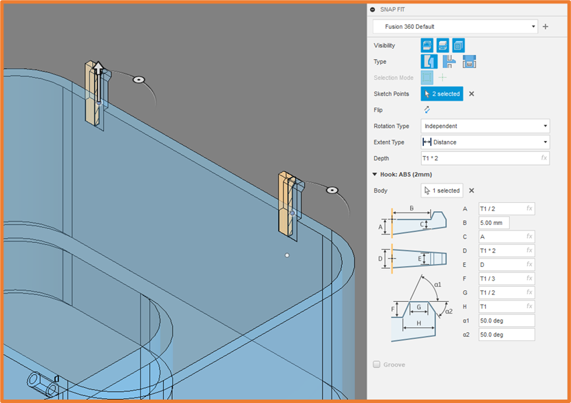
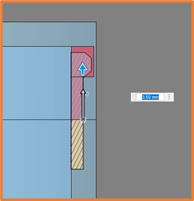
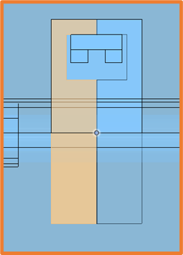
If you have both bodies visible, and your Hook intersects the second body, it will automatically cut out some clearance within the second body.
Geometric Pattern
The last feature we will look at today is the Geometric Pattern. This feature adds a few options onto the standard patterns available in Fusion. This will allow us to create patterns of three default shapes (Cylinder, Cube, and Sphere) otherwise we can use a custom shape. Allowing us to use any solid object in out file to create a pattern of.
We find these are great for detailed surfaces. Either to subtract/add geometry for grip, or creating holes in the face for ventilation.
The Geometric Patterns will fill an entire face, by default they will go up to the border, but we also have the option keep the border clear and ensure our pattern isn’t going over the edge. We set a size range for the shapes in the pattern which will drive the smallest to largest items, and spread the sizes between the two values.
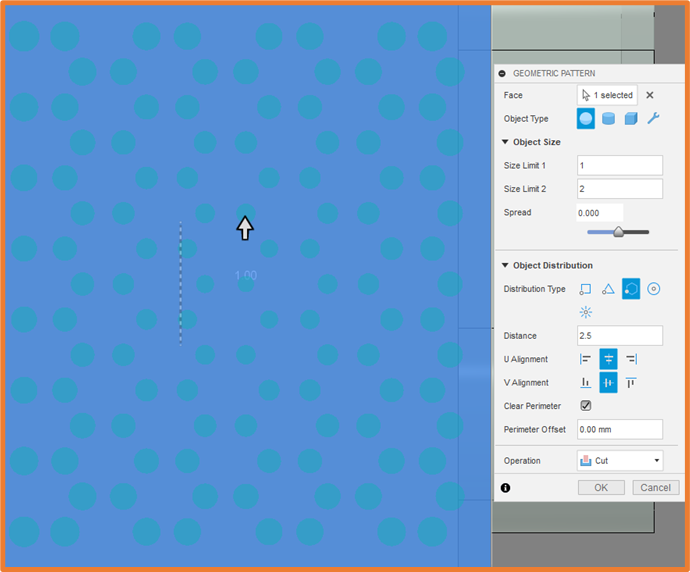
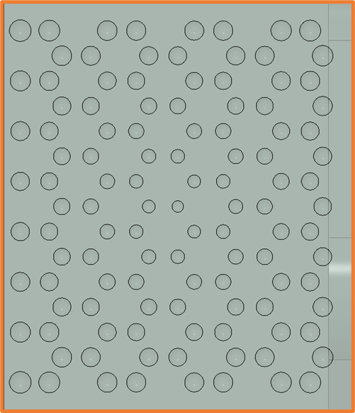
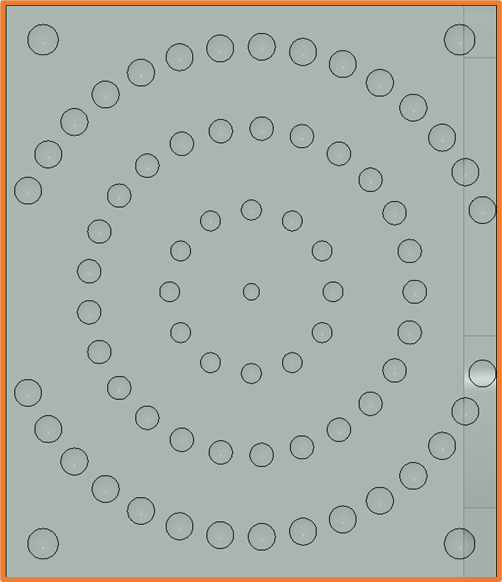
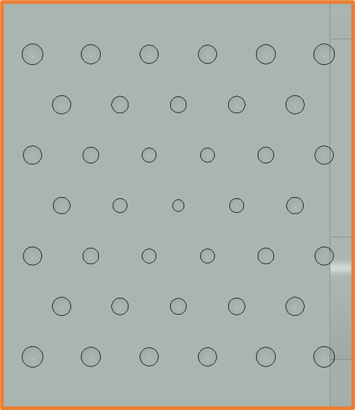
The Distribution of the pattern or the pattern of shapes can take one of five forms; Square, Triangular, Hexagonal, Circular or Arrayed. Which gives us a great variety of pattern options to choose from, with a lot of flexibility.
Still got Questions?
Book Training
Through hands-on exercises, you will acquire the key skills and knowledge required to design models using Fusion. It will teach you everything from product development to simulation and fabrication.
Contact Us
We are here to ensure you receive a consistently high service and quality solutions for your business needs. We promise you won’t regret speaking to us, and if we can’t help you, we will try to find someone that can.