
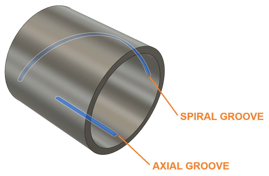
In Autodesk Fusion 360 CAM, it is possible to cut axial and spiral grooves into a turned part. This is achieved by leveraging planes and the Trace strategy. In this illustrated guide, we will explore how to CNC such grooves into the cylinder pictured below.
Step 1: Create Sketches and Planes
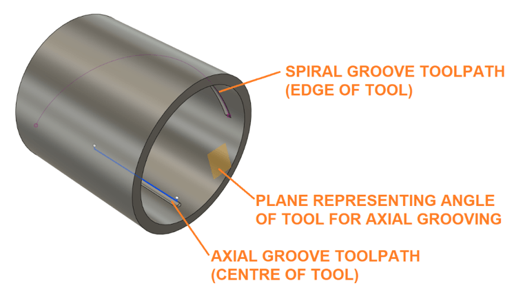
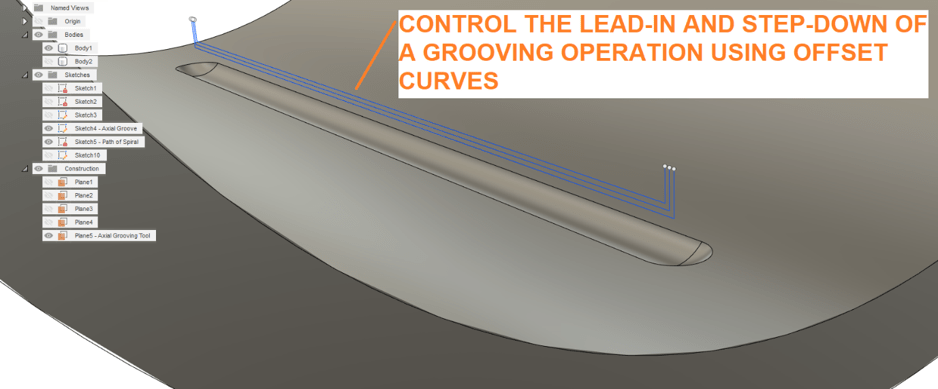
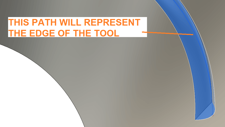
Begin by creating sketches that will govern the path of the tooling. In this example, the axial groove has three sketches representing the centre of the tool incrementally cutting into the material. The tool cutting the axial groove will be on an angle, governed by an angled work plane. The spiral groove will be governed by a sketch representing the edge of the tool.
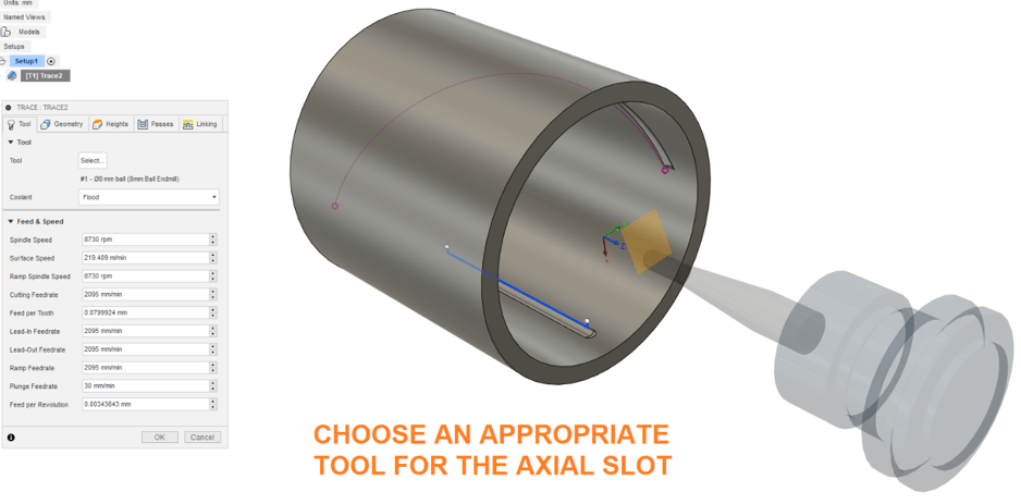
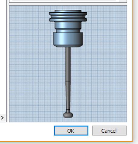
Step 2: Create a ‘Trace’ cutting strategy for the axial groove. Choose an appropriate tool. In this example, a ball-nose cutter is used, although a lolly-pop cutter may be warranted.
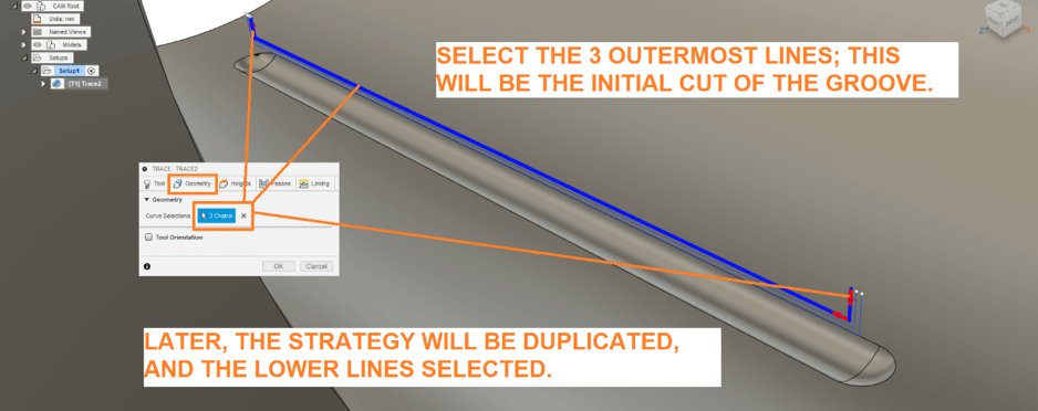
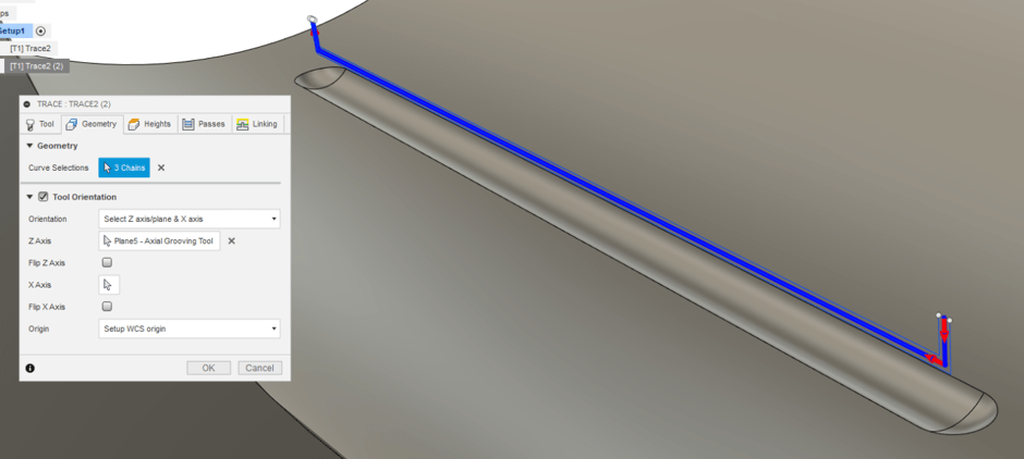
Step 3: Define the tracing path Under the geometry tab, click the topmost curves to guide (‘trace’) the tool. Click the red arrows to control the approach of the tool.
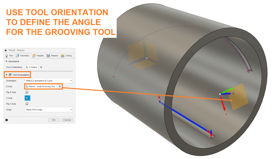
Step 4: Define the orientation of the tool If the tube is long, or if there is not enough clearance for the shaft of the tool, it may be necessary to angle the tool. To achieve this, tick ‘Tool Orientation’ under the Geometry tab, and select the angled plane.
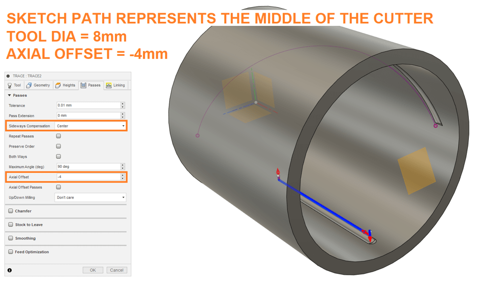
Step 5: Define tool compensation and axial offset
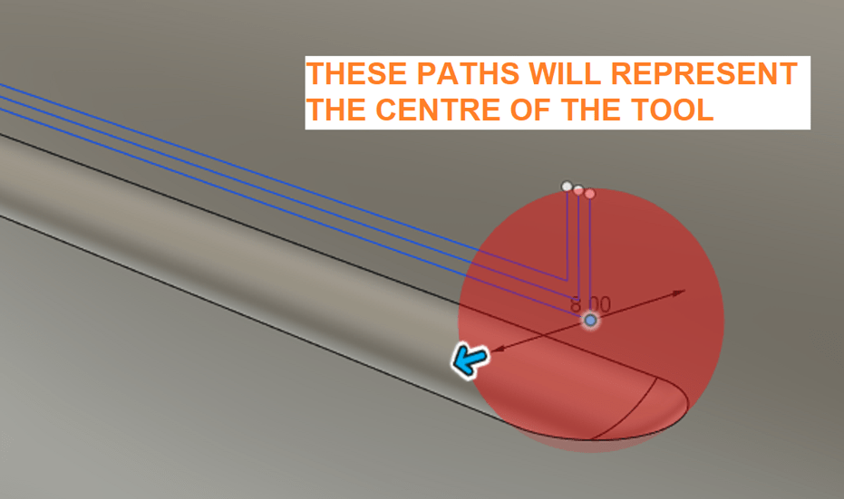
As the sketch we created represented the middle-centre of the tool, we will use the following settings under the Passes tab:
- Sideways compensation = centre
- Axial offset = -0.5 * tool diameter = -4mm
Click ‘OK’ to create the toolpath.
Step 6: Duplicate and adjust the toolpath to create step-downs To manually define step-downs, duplicate the toolpath, choosing the incrementally lower paths.
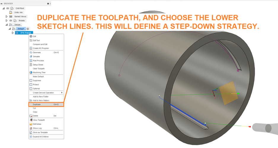
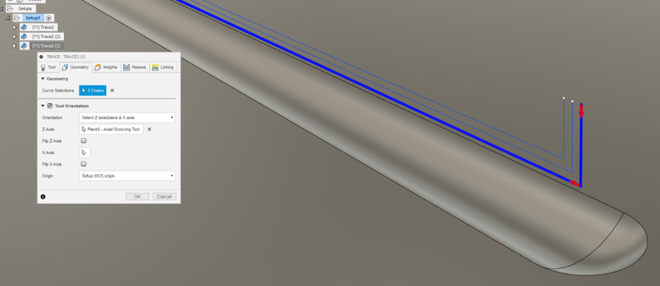
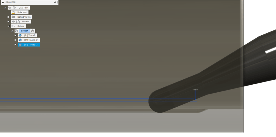
The paths we created incrementally cut the axial slot. However, we can see that on this angle, the ball-nose cutter will cut too much material at lead-in. Perhaps a lolly-pop cutter would be more suitable.
Step 7: Choose an appropriate tool for cutting the spiral groove In this case, the tool will be approaching axially. As such, the shaft must be narrower than the cutter. This approach will cause issues if the spiral is steep.
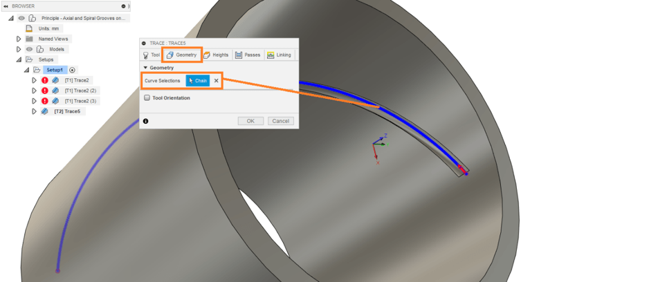
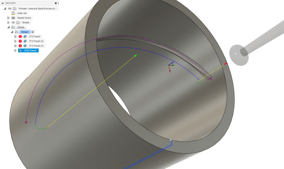
Step 8: Define the toolpath by selecting the curve Create a new trace strategy. Under the Geometry tab, choose the sketch line that followed the edge of the spiral groove.
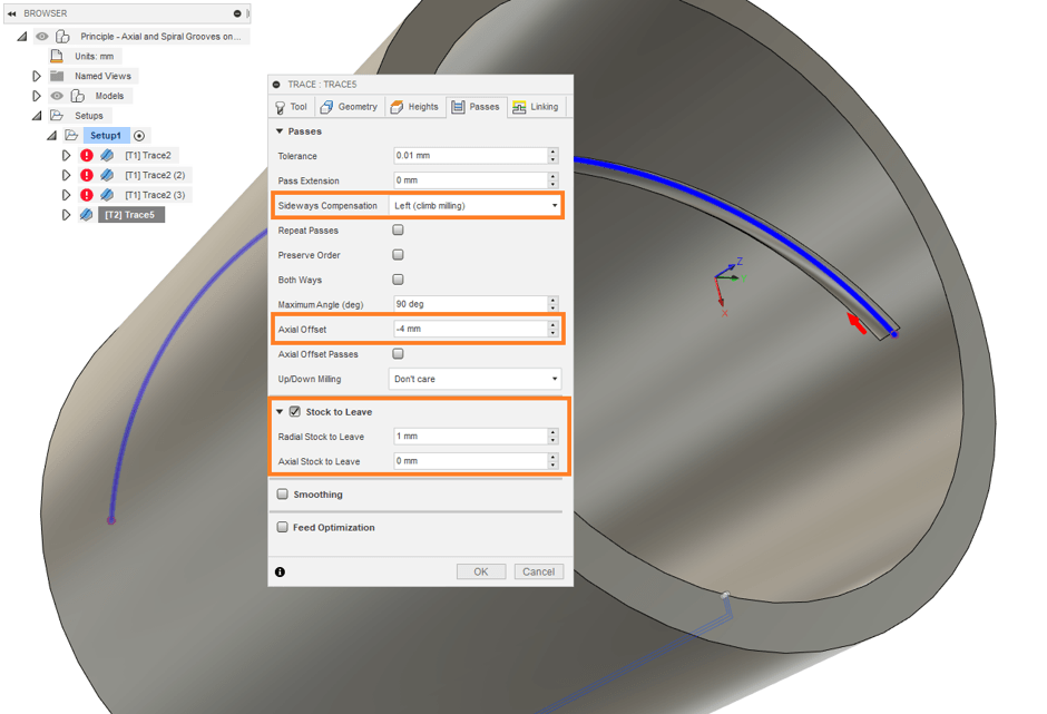
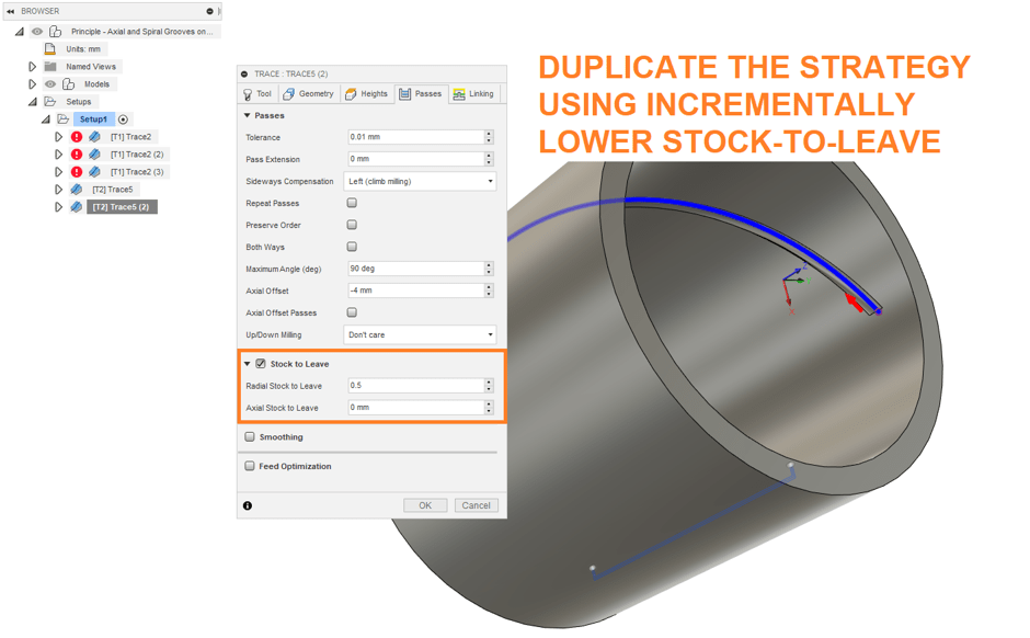
Step 9: Adjust sideways compensation, axial offset and stock-to-leave.
As the sketchline was to indicate the middle-edge of the cutting tool, we need to make the following adjustments under the ‘Passes’ tab:
- Set Sideways Compensation to Left (climb
milling); click the red arrow to ensure that the tool is on the appropriate
side. - Axial offset = -0.5 * Tool Diamater = -4mm
Set the Radial stock-to-leave to 1mm. This will be incrementally decreased in subsequent operations to define step-down for the tooling.
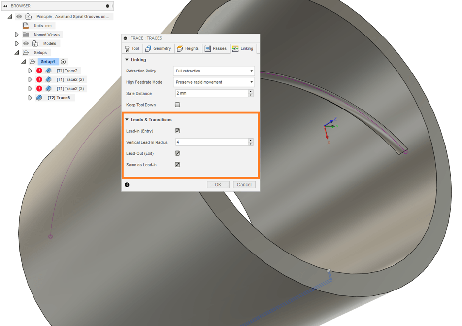
Step 10: Define Lead-In and Lead-Out The tool cannot be allowed to approach the cutting path axially as it would impinge on material. To circumvent this, under the ‘Linking’ tab, define Lead-in and Lead-out radii of 4mm.
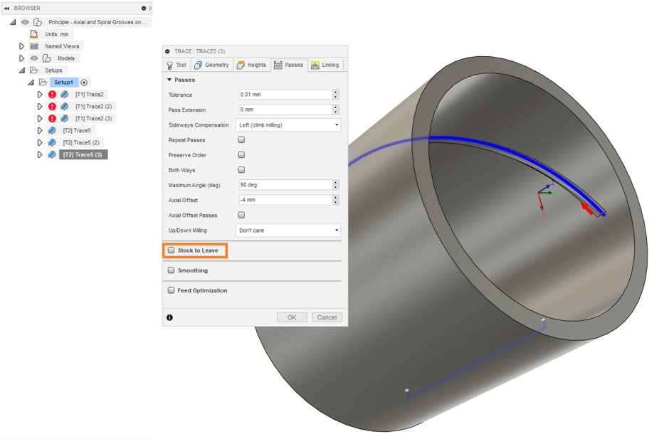
Step 11: Duplicate the strategy and adjust the radial stock-to-leave Duplicate the strategy a few times, and incrementally decrease the radial stock-to-leave. This will define step-down for the spiral grooving.
Conclusions
By making use of Trace strategies, we were able to define both axial and spiral grooving in Autodesk Fusion 360 CAM. If you are interested in learning more or would simply like a refresher on modern CAM techniques, get in touch with Man and Machine. Our expert applications engineers will have you proficient in no time!
Still got Questions?
Book Training
Through hands-on exercises, you will acquire the key skills and knowledge required to design models using Fusion. It will teach you everything from product development to simulation and fabrication.
Contact Us
We are here to ensure you receive a consistently high service and quality solutions for your business needs. We promise you won’t regret speaking to us, and if we can’t help you, we will try to find someone that can.