
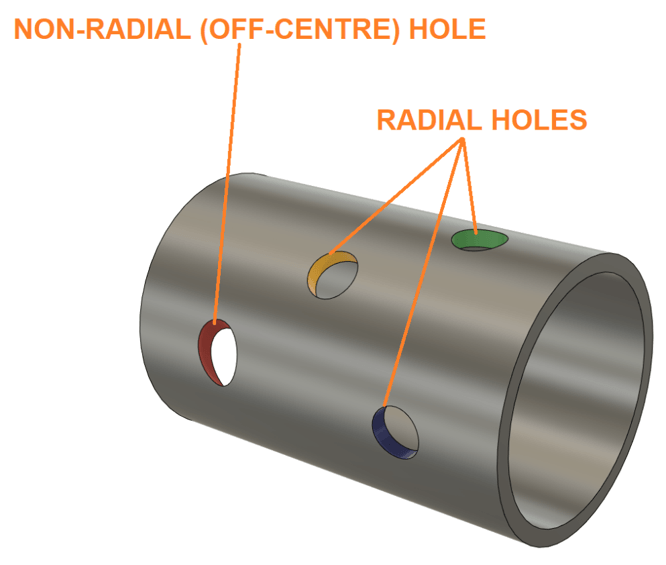
On a 4-axis lathe, it is possible to cut radial and non-radial holes into a curved surface. However, software can often have trouble identifying that a hole in a curved surface is indeed a hole. This can make it difficult to set up drilling operations. In this quick blog, we’re going to explore the quickest, laziest, and most reliable way to cut a hole (radial or non-radial) into the side of a pipe using Fusion 360 CAM.
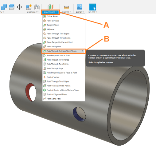
Step 1: Create a work axis for each of hole
A. Click the ‘Construct’ panel.
B. Click ‘Axis Through Cylinder/Cone/Torus’.
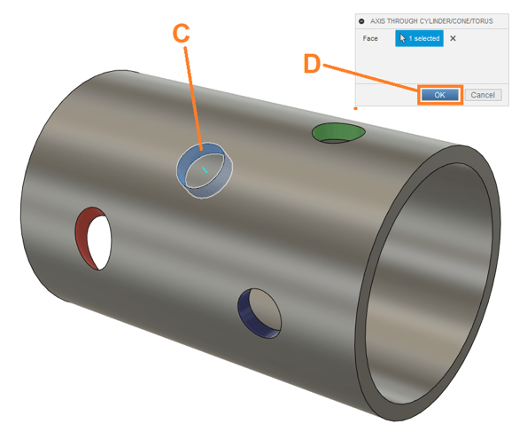
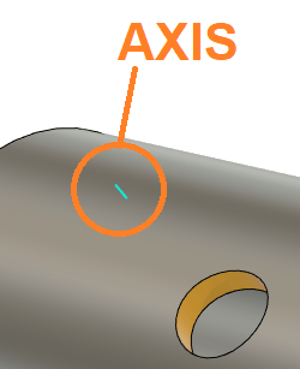
C. Click the rim of the hole.
D. Click ‘OK’.
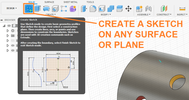
Step 2: Create a sketch on any surface
Create a sketch. The surface on which it is created does not matter; any surface will do.
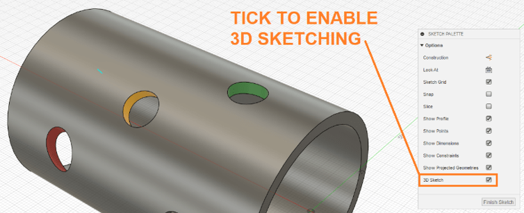
Step 3: Enable ‘3D Sketch’ within the sketch
Toggle on the 3D Sketching capabilities by ticking ‘3D Sketch’.
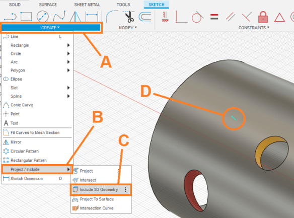
Step 4: Project/Include Geometry for each work axis
Include the axis of the hole in the sketch. To achieve this:
A. Click the ‘Create’ panel.
B. Click ‘Project/Include’,
C. Click ‘Include 3D Geometry’.
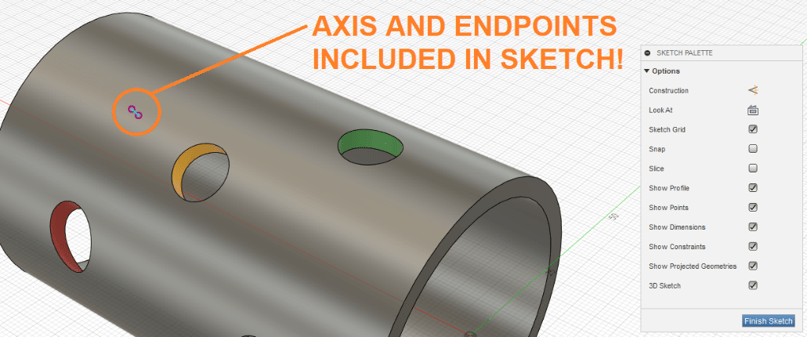
D. Click the axis. Click ‘OK’ to confirm
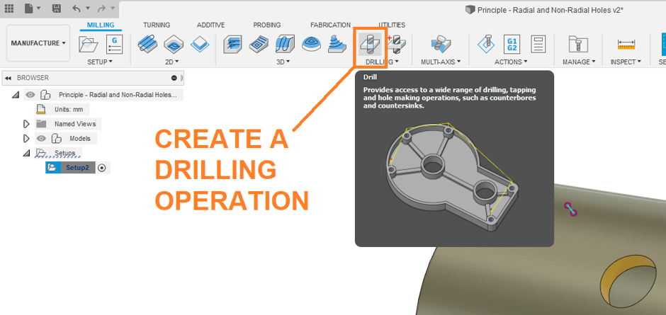
Step 5: Exit the sketch, enter the CAM environment, create your turning setup, and create a drilling operation
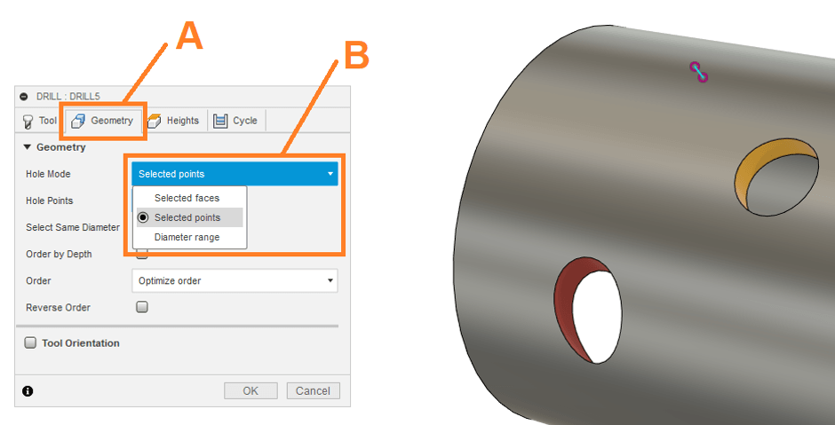
Step 6: Define the geometry for the drilling
You will find that Fusion sometimes cannot recognise a hole on a curved surface. To get around this, we are going to use the projected axis to direct a drilling operation. To achieve this:
A. Click the ‘Geometry’ tab.
B. Change the Hole Mode to ‘Selected Points’.
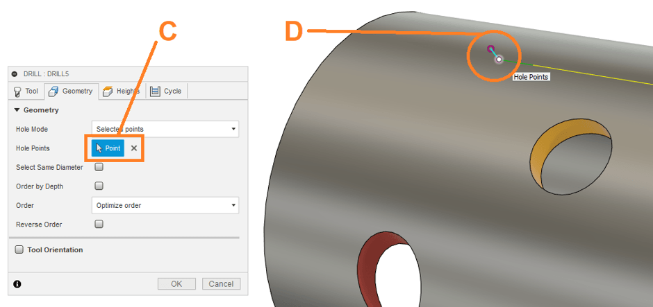
C. Click ‘Point’.
D. Click one of the points on the projected axis.
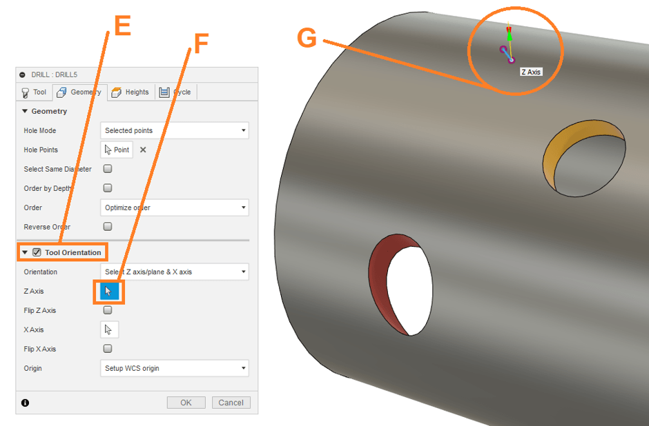
E. Tick ‘Tool Orientation’. This will direct the angle of attack of the drill.
F. Click ‘Z-Axis’.
G. Click the projected axis.
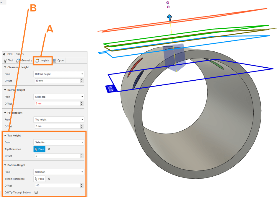
Step 7: Adjust the levels for the drilling strategy.
Because we used a projected axis to define the angle of drilling, we need to manually define the levels where drilling will begin and end. To do this:
A. Click ‘Heights’.
B. Adjust the heights until the drilling begins just above the hole and ends past its interior lip.
Conclusion
Wonderful! We have explored the laziest way of cutting these complex holes on 4-axis lathe using Fusion 360 CAM. If you’d like to learn more about Fusion, CAM or anything Autodesk, don’t hesitate to get in touch with Man and Machine. Our expert engineers will get you up to speed in no time!
Still got Questions?
Book Training
Through hands-on exercises, you will acquire the key skills and knowledge required to design models using Fusion. It will teach you everything from product development to simulation and fabrication.
Contact Us
We are here to ensure you receive a consistently high service and quality solutions for your business needs. We promise you won’t regret speaking to us, and if we can’t help you, we will try to find someone that can.