
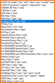
VRED allows you to import a wide range of file formats, from Autodesk programs such as Inventor’s Assemblies, Maya Files, to Sketchup files, as well the universal STEP files. Below are a few other file types that can be used.
Before you import your file though, you will want to get your environment set up and ready for the model. I will give a brief overview of each element, and some examples on how to set this up.
Asset Manager
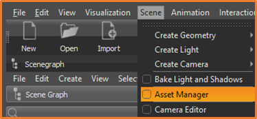
If you want to use VRED to its full extent you should use VRED’s existing materials as these have been created to get the most out of the renders. As of 2020 the Asset Manager is a separate install, so you will want to ensure that this has been installed too, to make the most out of your model.
Once installed you can find the Asset Manager under the Scene menu.
Within the Asset Manager you will find some basic Geometry, Materials and Environments that are a great starting point your scenes.
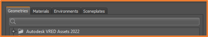
Geometries allow you to select from a small range of great quality car parts, including Interior, Exterior and Tires. You also have a range of people you can place in your scene to give it that added sense of scale.
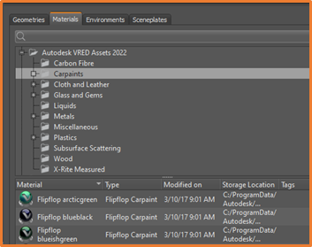
Materials are assigned to each part, and greatly impact the look of your renders. As stated earlier using the VRED Materials will improve the look of the final product as these have all been fine tuned to work with the software. When you import your models they will come in with their own materials, it is usually best to convert these to matching materials from this database. More on this a little later…
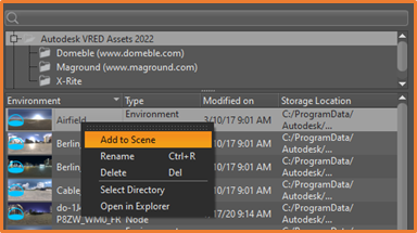
Environments are very important for getting the best output possible, you will want the highest quality backdrop to add to the render of your model. The environment will also act as the reflection on your more reflective materials. This adds great realism to the product, and further iterates why you want the best quality environment for your scene. Once you have found your environment, simply right click, and select Add to Scene.
Shadow Planes are much like the ground plane, this will be the surface where your part creates the shadows and gives a bit more depth to the renders. These are generally included within the VRED Assets.
If you have any of your own Geometry or Environments that you want to add you can easily import these too. You will need to point VRED to their folder location, and load them in from there.
Importing your file
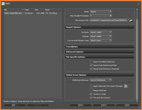
Once you have set up your scene you can import your model by simply clicking on the Import option in the top right, and navigating to the file you would like to bring in. As stated before, there are a great number of file formats that can be imported. Once you have selected your file you will be given the following window, take some time to look at the various settings available when importing. The main ones to look for are Centre in Origin and Put onto the Ground. We will apply the materials from the Asset Manager in the next few steps so you can leave this unchecked. Once you are happy click Import.
Transforming
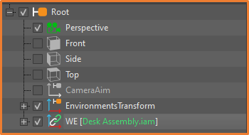
Once your model is in, you will want to move and rotate it into position. If you haven’t already, you can turn the Scene Graph on, this will show all the objects in the scene. For visual confirmation I usually toggle Wireframe on in the main toolbar. Select the Top-Level Assembly in the scene graph which should now highlight in the scene.
Then toggle Transform, again in the main Taskbar, you will then see the transform arrows in the X, Y and Z direction. To move the model in each direction, hold shift while clicking and dragging the relevant arrow. You can click and drag the relevant square to move your part on a plane.
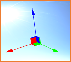
Hitting Shift+E switches to rotational control, where you again have the corresponding X, Y and Z rotation.
Assigning Materials
Once you have positioned your model you are ready to assign materials to the individual parts. When you import your models they will generally come in with preassigned materials. You can either assign VRED materials based on these material groups, or by using the Scene graph and selecting the individual parts.
Assigning by Material
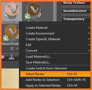
In the Materials Editor, you will have a list of materials that are currently being used in the scene. Simply select each of the materials and hit Ctrl+N (Right click>Select Nodes) this will select all nodes or parts that have this material assigned.
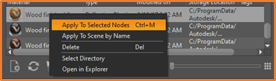
Open the Asset Manager, navigate to the material you would like to replace these with, select the required material then hit Ctrl+M (Right click>Apply to Selected Nodes).
Assigning through Scene Graph
In the Scene Graph, navigate to the top level assembly, from here you can expand the assembly into its individual parts. Select each part and assign the required material through the Asset Manager.
Open the Asset Manager, navigate to the material you would like to replace these with, select the required material then hit Ctrl+M (Right click>Apply to Selected Nodes).
You can select Multiple parts, or nodes, by control clicking individual items within the Scene Graph.
Navigating through Space
At this point it is good to know how to navigate around your model.
Panning is done by holding the middle mouse (Scroll) button on, and moving it around much like you would in Inventor.
Orbiting is done around an orbit point, which is automatically set at the origin. You orbit by left-clicking and holding the mouse, then as you move the mouse around it will orbit in the direction you move, as if you are rotating around the orbit point. The orbit point can be changed by double right-clicking on a surface you would like to orbit around.
Zooming can be done by either scrolling in or out with the mouse wheel, or by holding the right-click and dragging up or down.
Real time Rendering
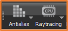
Before you push out a render, you may want to have a quick preview of the result, this can be done in real time using either CPU or GPU Raytracing. This will slow your machine down, so only use this if you don’t have any graphic rich programs running in background. The image will look grainy as it is only running through the Ray Tracing, so once you have found the correct angle and you are happy with the lighting, you can turn on Antialias. This will smooth out the render and give a better idea of the final output.
You can then make any final tweaks, and head over to the rendering options…
The Final Render

All that is left now is to push out a beautiful image of your design. Clicking on Render will take you to the Render Settings window, where you can choose from a great number of options. Since this is just an introduction, we won’t go over all the settings but feel free to play around with the different outputs.
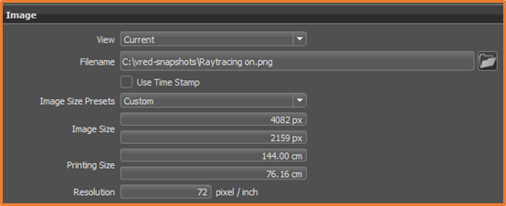
The main settings to check will be:
Image size, the larger the image, the longer it will take to produce. There are some hand presets if you do not require a custom size.
View is the setting you would change if you had other cameras set up within the scene. This would allow you to choose one with which you render your image. Ensure this is set to current.
All that is left is to hit Render and wait for the result.
Still got Questions?
Book Training
This high end visualisation tool from Autodesk will help you create 3D models, rendered images, animations and games using smart workflows and tools which save you time without affecting your output.
Contact Us
We are here to ensure you receive a consistently high service and quality solutions for your business needs. We promise you won’t regret speaking to us, and if we can’t help you, we will try to find someone that can.