
Why do we bother with 3D models? Didn’t we get to the moon just fine with 2D drawings? The truth is that 3D models have so much more to offer than pretty visuals. Read on to discover the great things that become possible when working in the third dimension!
In a Nutshell
By using 3D models, it becomes possible to easily:
- Modify geometry, and have all related 2D
drawings change automatically, - Create Bills of Materials and Parts Lists,
- Perform engineering analyses,
- Create CNC machining toolpaths,
- Perform interference checks, calculate mass and
centre of gravity, etc. - Create animations, visualisations and renderings,
and much more.
Quick Modification of Geometry and Drawings
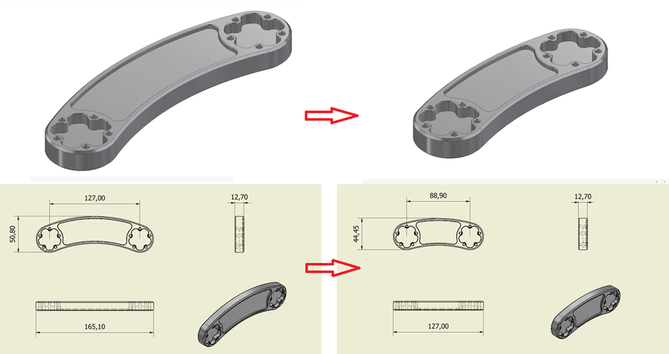
Perhaps one of the greatest strengths of 3D modelling is the ease by which geometry can be reworked. Consider the case of a single part that must be modified. In the past, when working in 2D, this would entail the modification of not only the part’s drawing, but also the drawings of each of the subassemblies and assemblies in which it participated; a time-consuming and error-prone process.
Conversely, when working in 3D, not only is modifying a part a far simpler process, but its updated geometry is also automatically disseminated to all of the subassemblies and assemblies of which it is a participant. Furthermore, all 2D drawings derived from these 3D parts, subassemblies and assemblies are also automatically updated, saving both time and the possibility of error.
Automatic Bills of Materials and Parts Lists
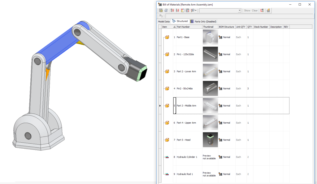
It has traditionally been the hard lot of the draftsperson to manually count out parts when putting together BOMs and parts lists. This is because, ordinarily, 2D drawings do not formally track the individuality of parts; each part are just lines on a page until they are interpreted by the reader.
However, when working with 3D models, the creation of BOMs and parts lists becomes an automatic process. Due to the file architecture requiring users to create parts and subassemblies formally, BOMs and parts lists are populated automatically as these components are put together into an assembly. Magic!
Engineering Analyses
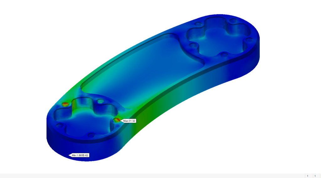
Modern engineering analysis tools (including FEA, dynamic simulation, etc.) require some sort of 3D model. If a design is expressed as a 2D drawing, a 3D model must be created specifically for this purpose. However, if the design is already expressed as a 3D model, then analysis can begin immediately. Not only does this save time and the possibility of introducing further errors, but it also makes possible an iterative approach to engineering.
Consider the task of optimising the wall thickness of a metal body, with the goal of minimising the weight while maintaining structural integrity under expected loading. If the design is created as a 3D model, a parameter can be used to drive the wall thickness. For a given thickness, a stress analysis could be performed. If the results show that the design is far from failure, then a user could simply return to the 3D model, modify the wall thickness by tweaking its relevant parameter, and rerun the simulation. In this way, 3D models allow designs to be more easily optimised.
Machining Toolpaths
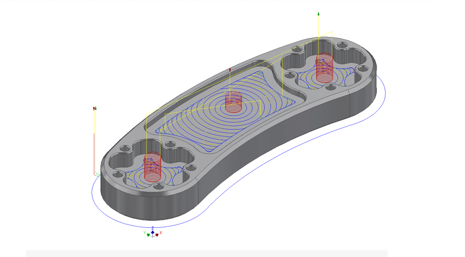
In the past, machining was largely a manual process. Skilled machinists would interpret 2D drawings, and from these, decide upon the best machining strategies to employ. However, with the advent of CNC, this process is becoming increasingly a matter of programming. Today, it is common practice to specify all of the machining toolpaths (along with the NC code) required to create a component before the design ever leaves the office. The creation of the toolpaths in this way depends on the existence of a 3D model. Not only does this put machining strategies in the hands of the design office, but it also allows engineers to take an iterative approach towards designing for manufacturability.
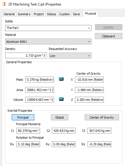
Automatic Geometric and Physical Data
When a component is designed in 3D, a plethora of data becomes automatically available to the user. Having specified both material density and geometry, 3D modelling software can easily output information of interest, such as mass, surface area, volume, centre of gravity, principal moments of inertia, etc. This is simply not possible if the design is manifest as a 2D drawing.
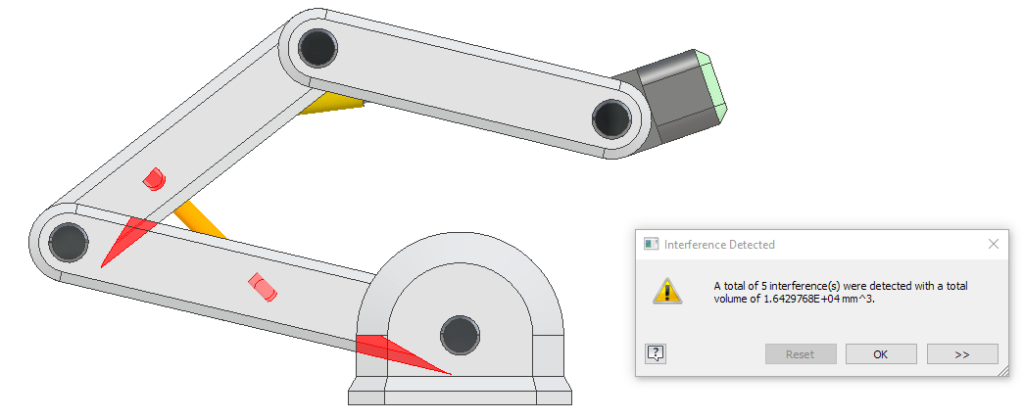
Ensuring that components do not interfere with one-another when placed in assembly is another important sanity-check for a design. With all components expressed as 3D models, this becomes extremely easy.
Create animations, visualisations and renderings
Lastly, when a design is captured in a 3D model, it becomes simple to create animations, visualisations and renderings. As a bonus, any modifications made to the designs are automatically carried over to these pretty outputs.
Conclusion
At its core, a design is an idea – one that must be shared with enough detail and fidelity to make collaboration possible. Traditionally, the medium of this sharing was the 2D drawing, and it has served us well, but it simply cannot keep up with the offerings of a 3D approach. This article just scratches the surface of what is possible when you start working with 3D models, and given the ever-rising expectations for quality and speed made of design offices, it is the logical option. If you wish to learn more about how your office can transition from 2D to 3D, please don’t hesitate to contact us at Man and Machine. We live and breathe all things CAD, CAM and CAE, and we’d be delighted to help you in the transition.
Still got Questions?
Book Training
Our range of Autodesk Inventor training courses will teach you how to create production-ready parts and assemblies through hands-on learning experience. Make sure you contact us to find out which course is best for you.
Contact Us
We are here to ensure you receive a consistently high service and quality solutions for your business needs. We promise you won’t regret speaking to us, and if we can’t help you, we will try to find someone that can.