
The frame generator within Autodesk Inventor is a design accelerator that allows users to place structural sections from the Content Center efficiently. Being a design accelerator, the frame generator is used in the assembly environment to place frame members without having to first create the part manually.
Structural Member Placement
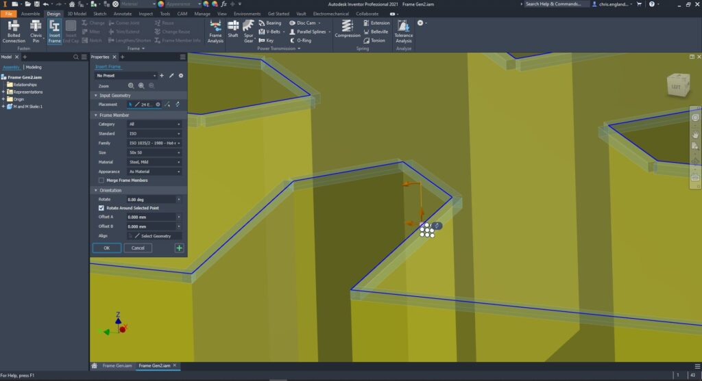
Structural members have a driven by length using skeleton geometry for the frame to be based on. A user can create skeleton geometry that is solid or surface bodies or even use unconsumed sketches. The user can pick an edge or two points allowing them to run a structural section along the edge or between the two points. The frame member can then be orientated easily using a check box system. In 2021, the alignment option appears on the frame member but in prior releases it was on the menu.
Finishes
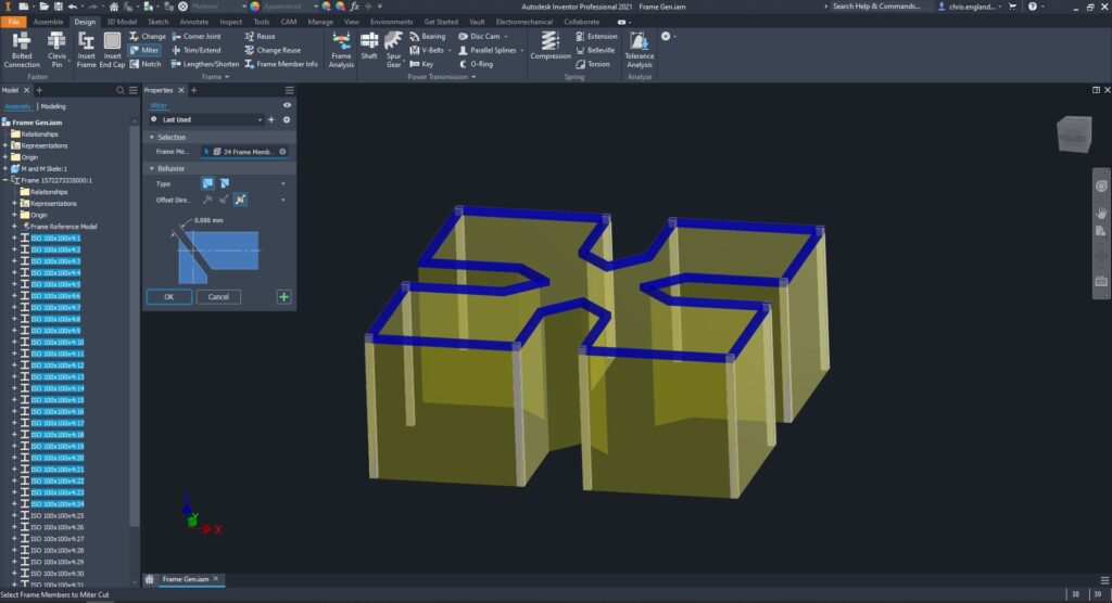
Once the frames are placed, Inventor offers a range of tools for trimming, mitring and notching profiles. Although these tools are used in the top-level assembly, the changes made will affect the parts files, meaning the parts will reflect the true detail. The Inventor 2019.1 release also saw multiple enhancements to these features allowing users to group mitre selections.
End Caps
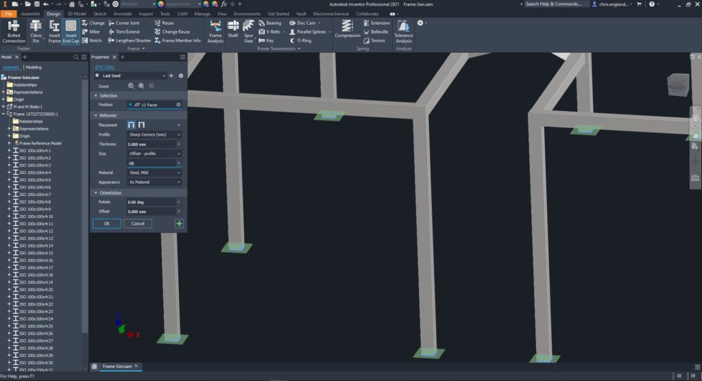
With the 2020/2021 Inventor release, Frame generator also now offers the option to add end caps to a frame member. Users can add end caps to a structural member or use it to create base/mounting plates to save time creating parts manually.
Pre-sets
Users can now save pre-set options in all the frame generator menus shown. This is helpful because users can save time by setting up defaults that a user reuses regularly. Things like mitre gaps, endcap offsets or preferred structural members can be stored for reuse.
Conclusion
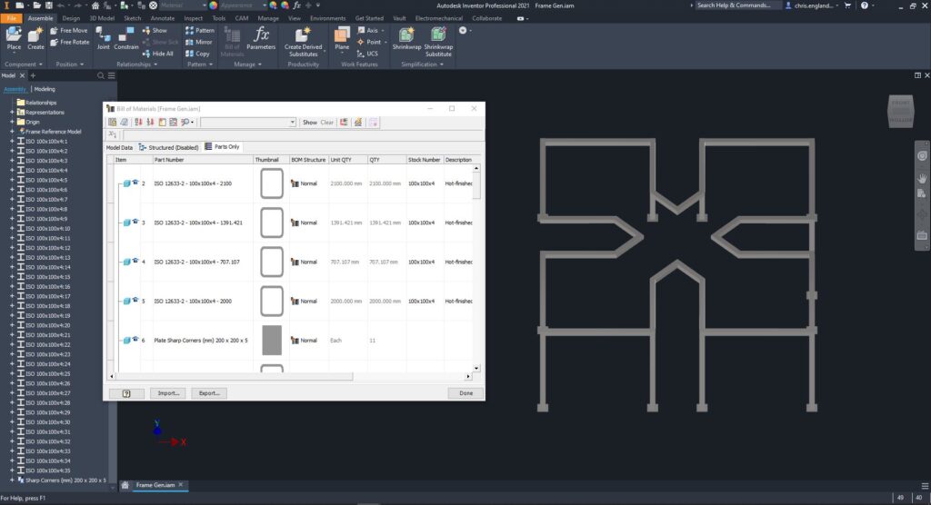
Inventor frame generator is great to do quick structural designs. It saves users time creating manual parts and affecting changes on each part individually. It allows for fast BOM take offs as members will automatically have length iProperties mapped. Working in the assembly environment enhances speed but each part is detailed and saved individually for creating manufacturing drawings.
Still got Questions?
Book Training
Our range of Autodesk Inventor training courses will teach you how to create production-ready parts and assemblies through hands-on learning experience. Make sure you contact us to find out which course is best for you.
Contact Us
We are here to ensure you receive a consistently high service and quality solutions for your business needs. We promise you won’t regret speaking to us, and if we can’t help you, we will try to find someone that can.