In line with Autodesk’s paradigm of having the model as the ‘source of truth’, it is possible to specify welding detail within an Inventor model. This is fantastically useful as it is also then possible to pull this information onto a 2D drawing. In this illustrated guide to weldments, we will explore the processes of converting an assembly into a weldment, defining welding details, and pulling this information onto a 2D drawing.
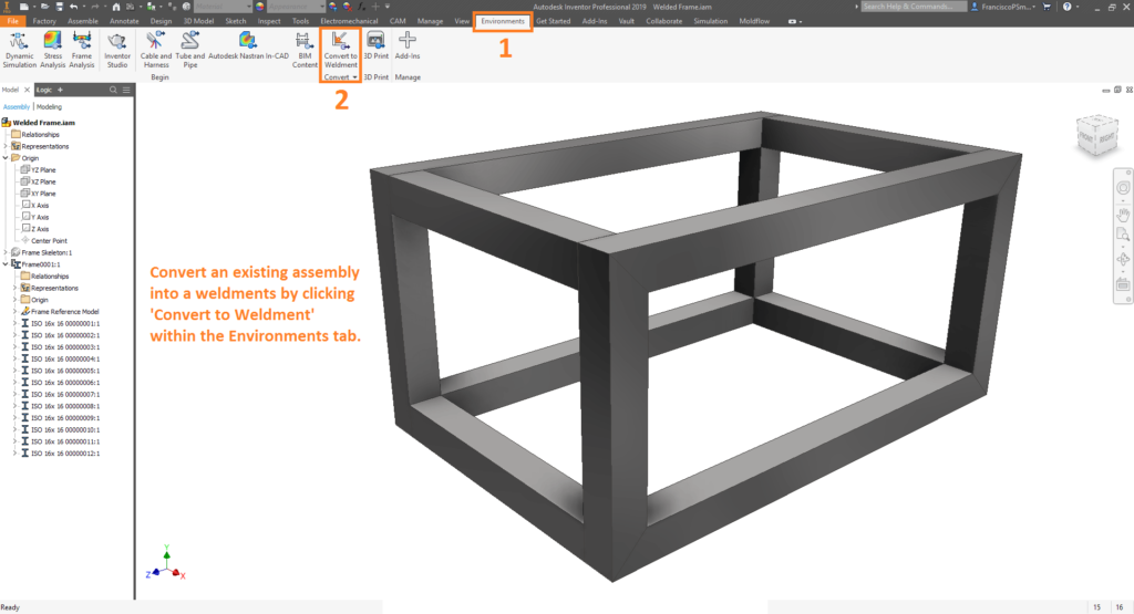
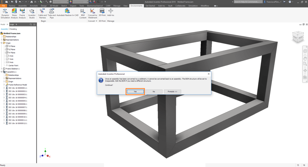
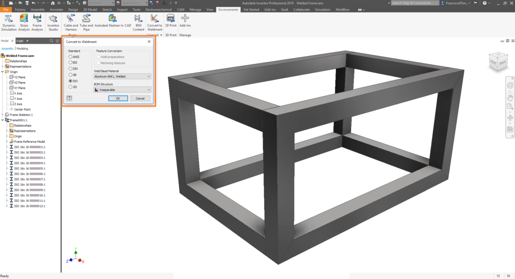
Step 1: Converting an Assembly into a Weldment
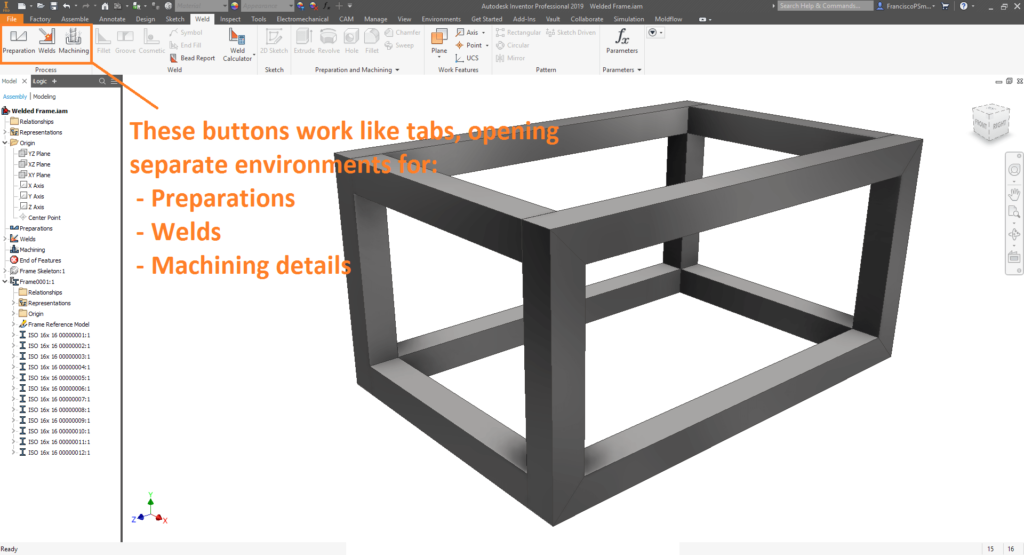
Step 2: Creating Welds and Specifying Weld Symbols
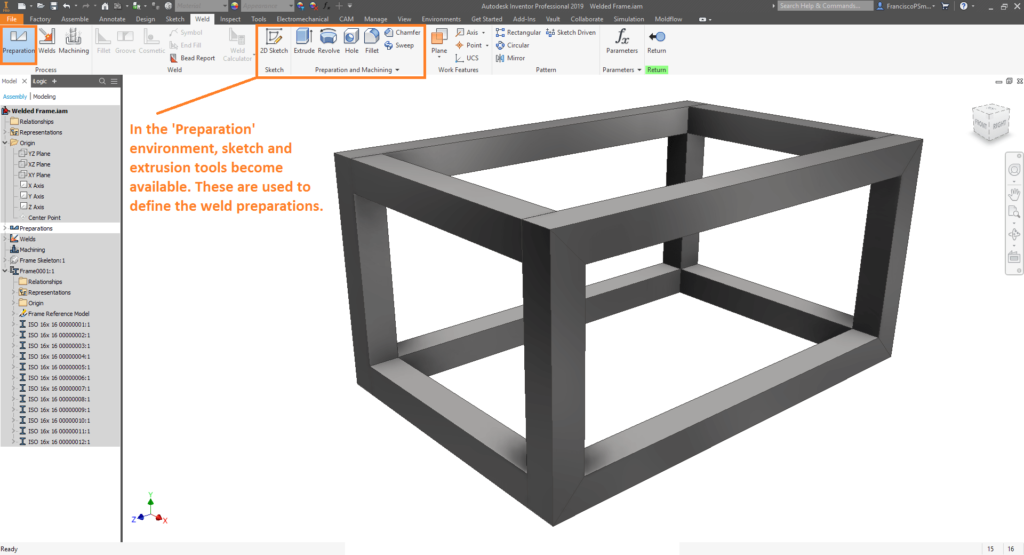
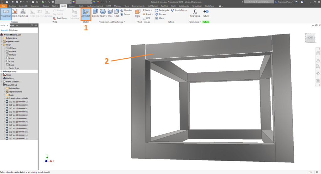
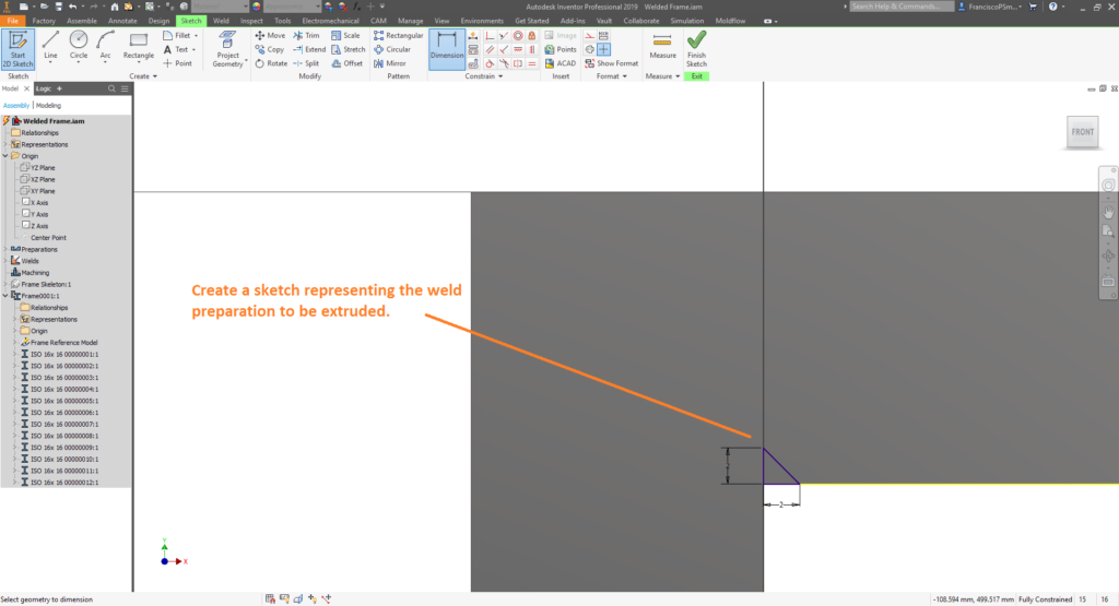
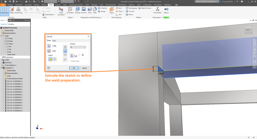
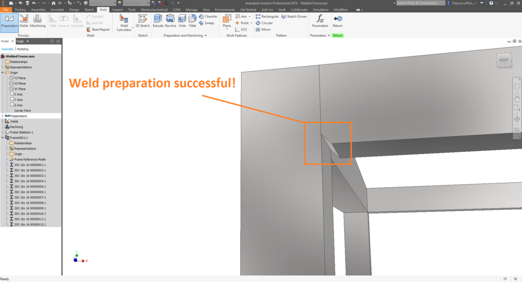
Part 2A: Weld Preparations
Part 2B: Welds and Welding Symbols
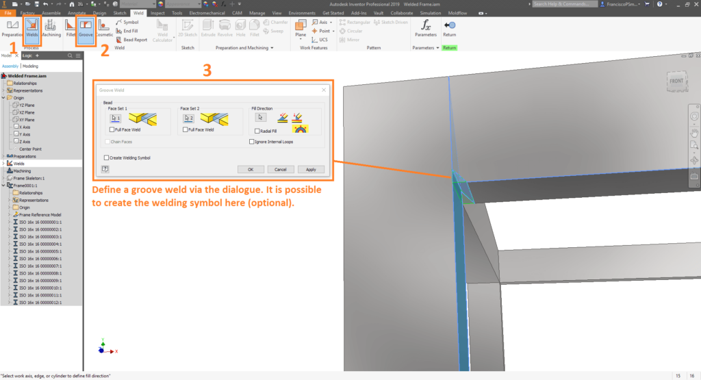
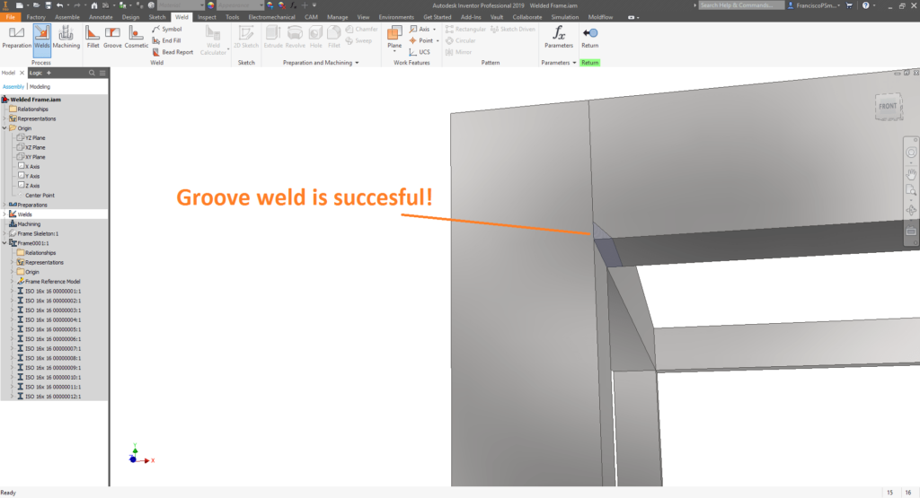
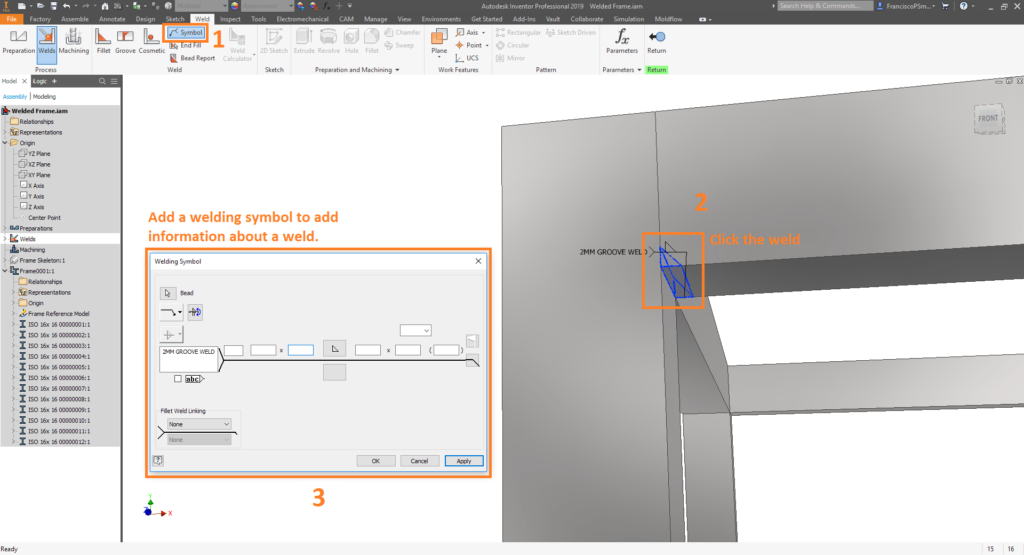
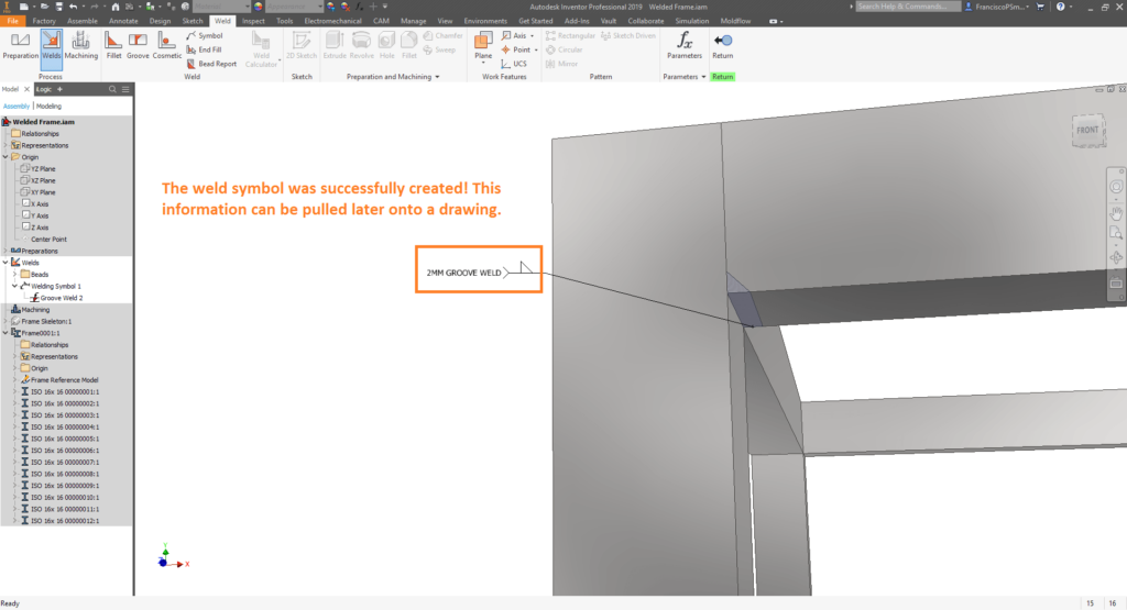
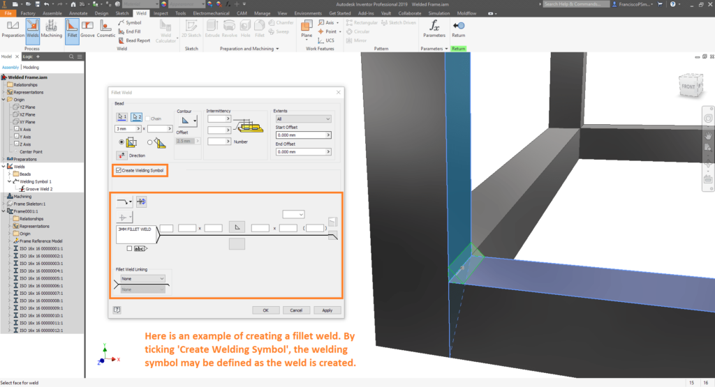
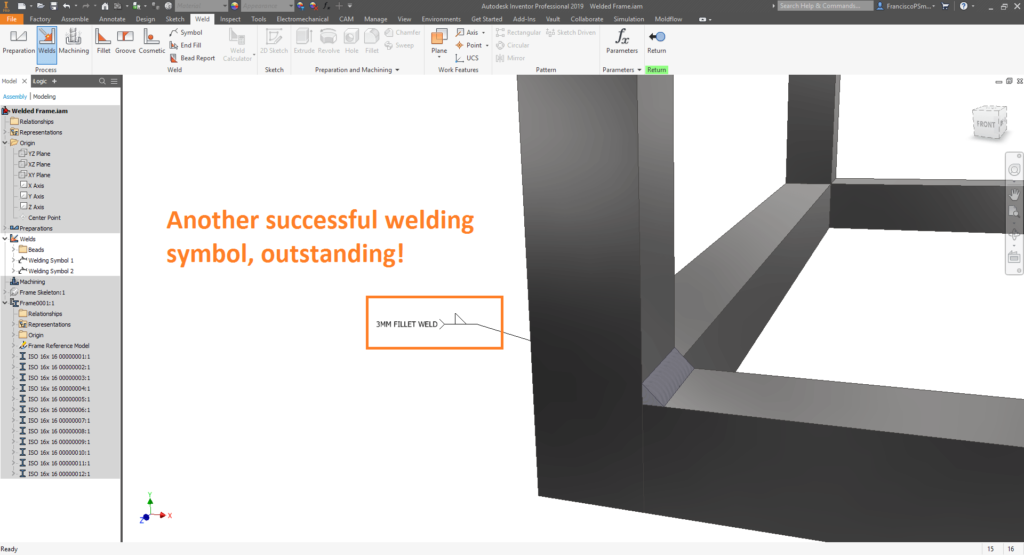
Part 2B: Welds and Welding Symbols
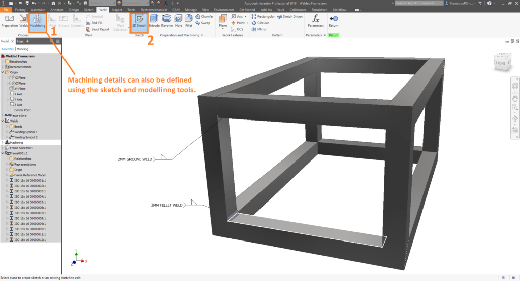
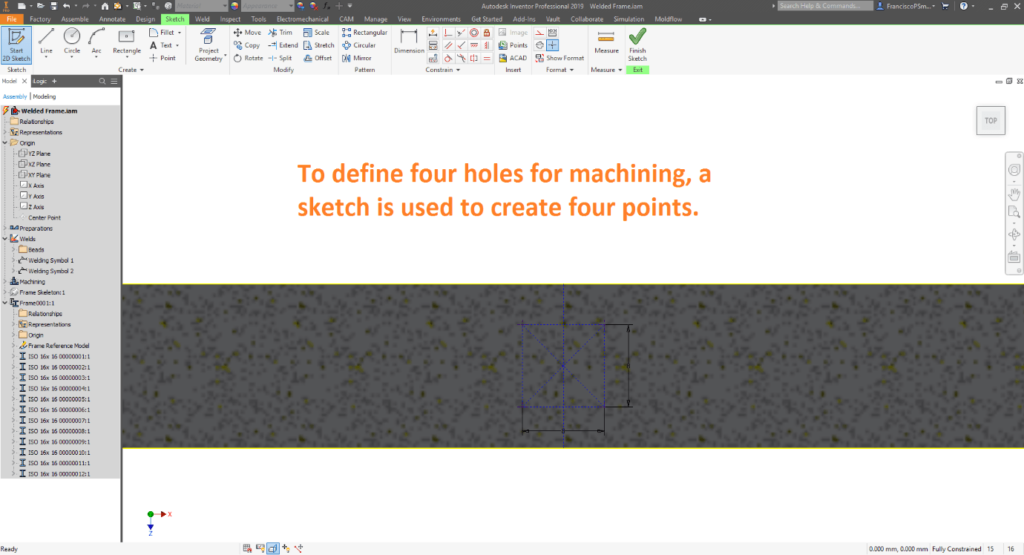
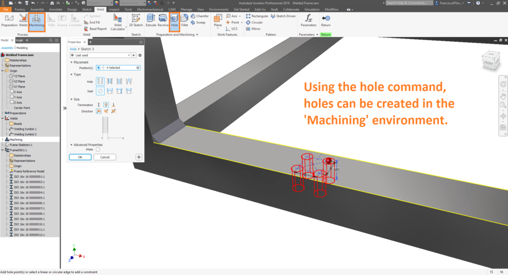
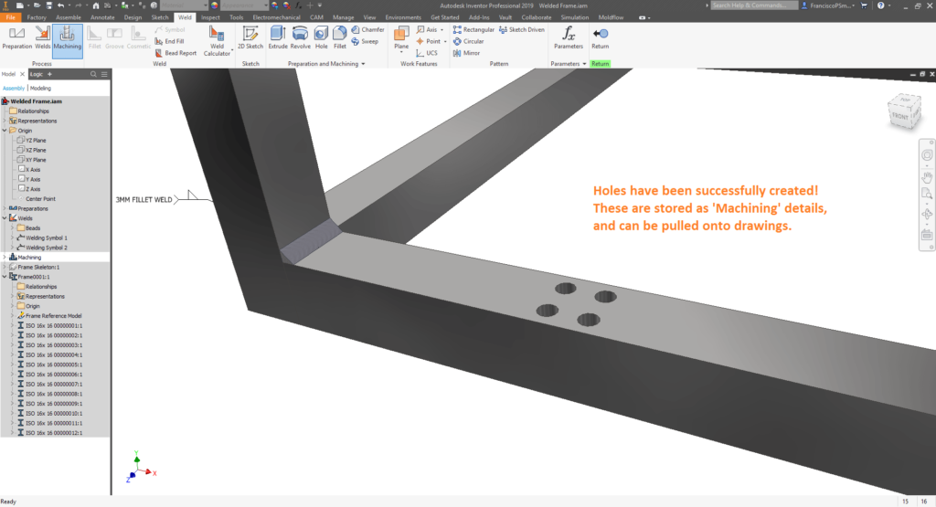
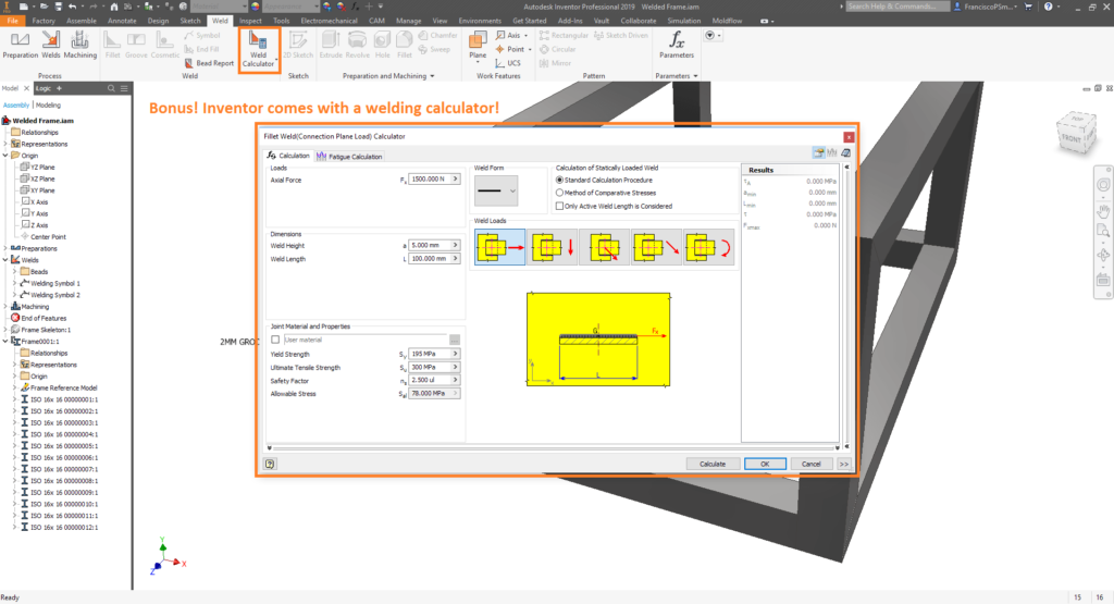
Bonus: Weld Calculations
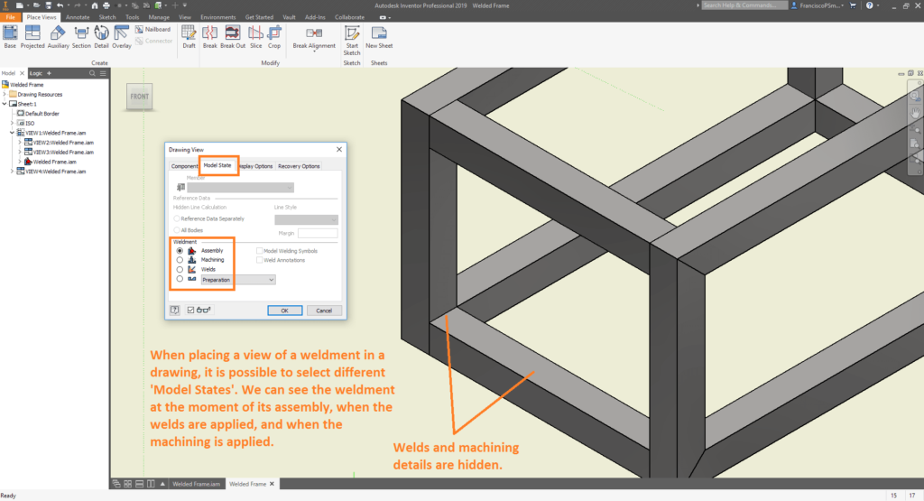
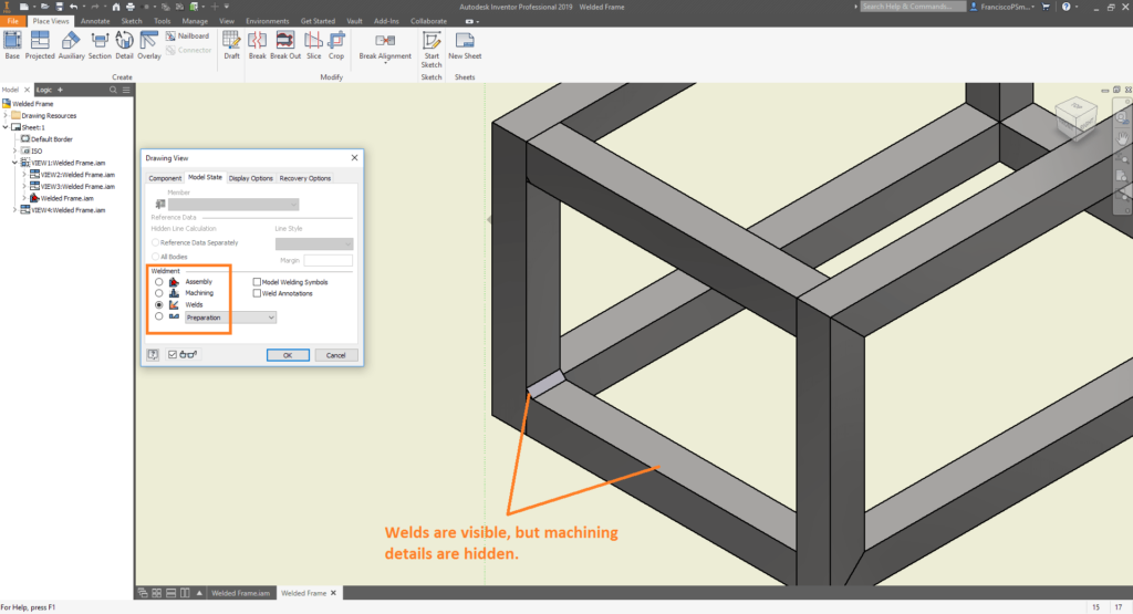
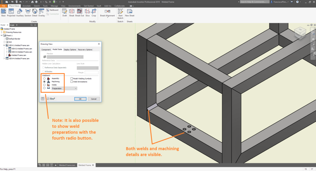
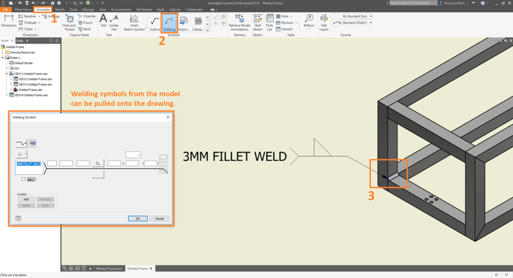
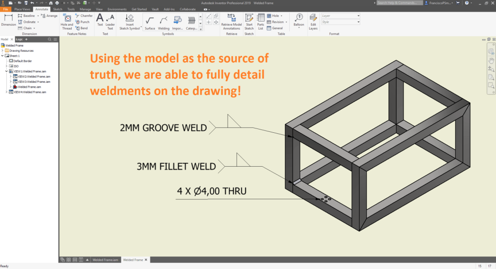
Step 3: Detailing Welds on Drawings
Conclusion
From this guide, you have seen how to define weldments in Inventor, and detail them in drawings. Through an excellent architecture, Autodesk have been successful in keeping the model as the source of truth. If you are interested in learning more, please don’t hesitate to contact Man and Machine. Our qualified engineers will have you an expert in all things Inventor in no time!
For more information on this blog post, or if you have any other questions/requirements, please complete the below form:
Related Links
Autodesk Inventor – Man and Machine
Autodesk Inventor Training – Man and Machine
Autodesk Inventor CAM Training – Man and Machine
Autodesk Product Design and Manufacturing Collection – Man and Machine
Inventor Training – Solid Modelling Introduction – Man and Machine
Autodesk Inventor – Autodesk Platinum Partner – Man and Machine