
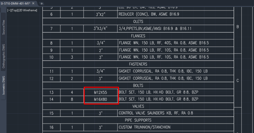
How do you display metric bolt sizes when working with imperial pipe components in a Mixed Metric Plant 3D project? Standard bolts sizes in imperial catalogues such as ASME are shown in imperial but in some mixed metric projects, it may be required to use imperial pipe sizes with metric bolt sets. This blog will detail how to configure your catalogues, specs and isometric configuration to show this style.
Editing the Bolt Sets
The first thing we need to do is to create a metric bolt set that we can use in our mixed metric project. This will be defined in the Catalog Editor with Inch nominal units, as we will be using this bolt set with ANSI fittings. However, we will specify metric bolt sizes and bolt lengths to comply with our standard bolt lengths.
Unfortunately, because we must specify Inch nominal units for our bolt set, we must use an Imperial bolt mapping standard to define our standard bolt lengths and this is the root of most bolt length issues in mixed metric projects.
To define the bolt mapping standard we must convert our metric lengths to inches by dividing by 25.4.
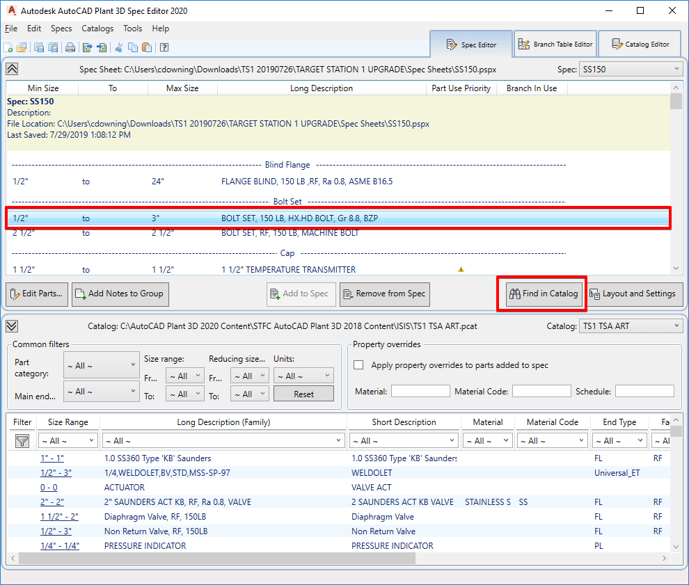
Open the relevant catalogues and create a Bolt Length Mapping standard for every catalogue that you have used bolt sets from in your specs. If you not sure what catalogues you have used for your bolt set you can open the spec, select the bolt set and use the ‘Find in Catalogue’ option as shown in the picture below.
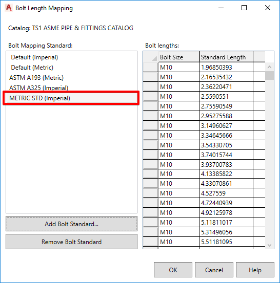
Once the correct catalogues are open in the catalogue editor you can create the Bolt Length Mapping. Select menu Catalogues > Edit Bolt Length Mapping.
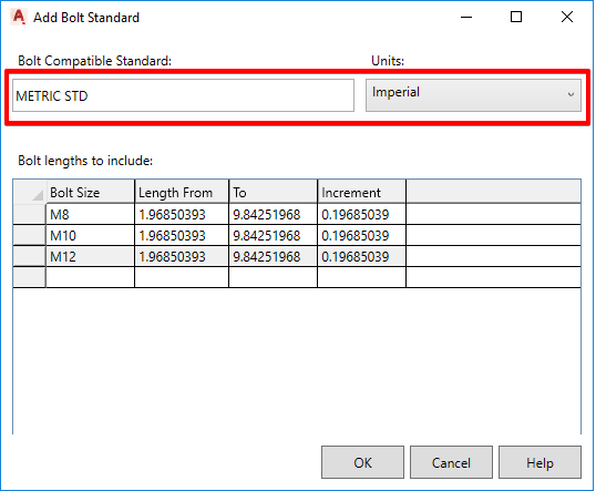
To create bolt lengths set to 5 millimeter increments using the following figures:
Length from = 1.96850393, Length To = 9.84251968, Increment = 0.19685039
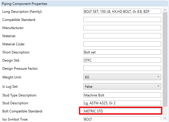
Next, we must edit the bolt set properties in the Catalogue Editor.
Set the bolt standard for each bolt set used to the next ‘METRIC STD’ standard.
Note: we must set the Is Lug Set flag to true and then back to false when we create our bolt set, otherwise the value may be set to NULL when we add the bolt to a spec – this would cause the default Flanged Joint connection setting to fail in Plant 3D resulting in Placeholder bolts being inserted.
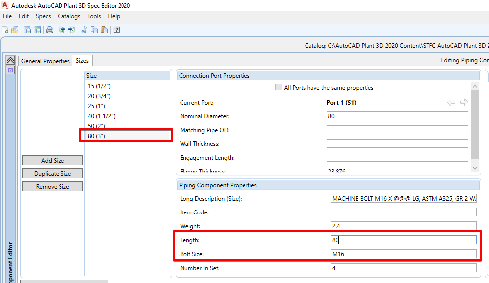
Then we need to edit the bolt length sizes in millimeters. Select Catalogues > Edit Catalogue in Metric Units.
Set the metric length and bolt size for each bolt in the imperial catalogue used.
When we revert back to; Catalogs > Edit Catalog in Imperial Units, we need to consider conversion errors.
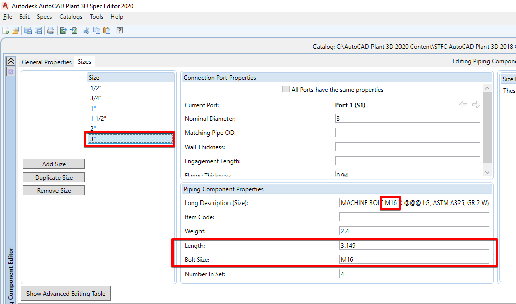
To compensate for this, ensuring that the correct lengths are selected, we truncate the imperial bolt lengths (inches) down to 3 decimal places, it’s recommended to round the number down as the software will always select the next length increment upwards; if the length in the 3D model is 79.99995 then the software will select the bolt increment 80 when creating the isometric BOM.
Save all the changes to the catalogue and update the spec with the changes.
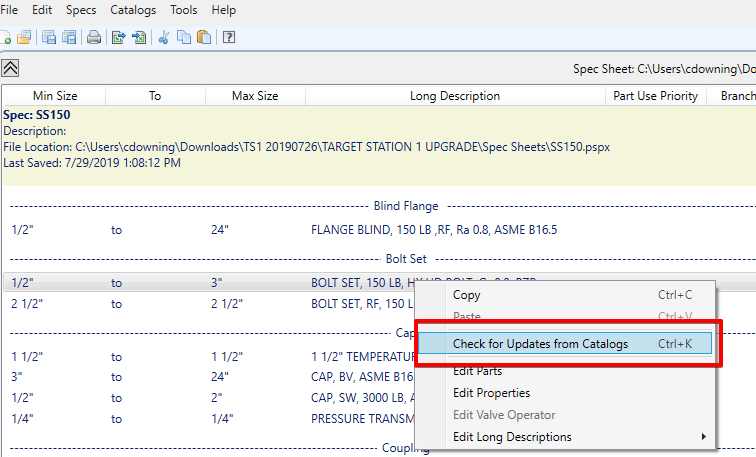
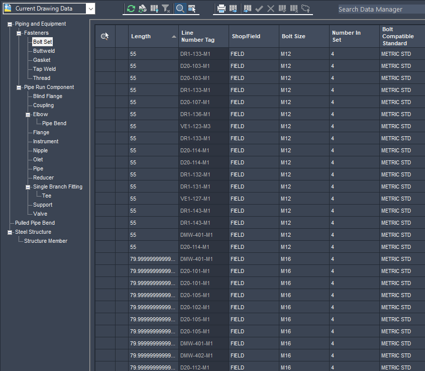
Open the 3D model and update the model with the new spec components. Check the data manager to ensure the changes have been made.
Isometric Configuration
Plant 3D uses a file stored in the Isometric folder called BoltSizeMapping.xml to find the values that are used for the bolt sizes.
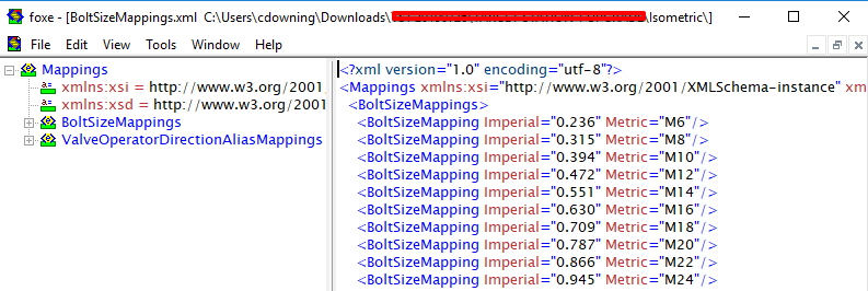
Create a mapping for each bolt size, the imperial size must be a decimal value of the metric bolt size, for example, M6 use the equation 6 / 25.4 = 0.236.
The unit’s style will be determined by the BoltDiameterStyle tag in the IsoConfig.xml file stored in the Isometric style folder.
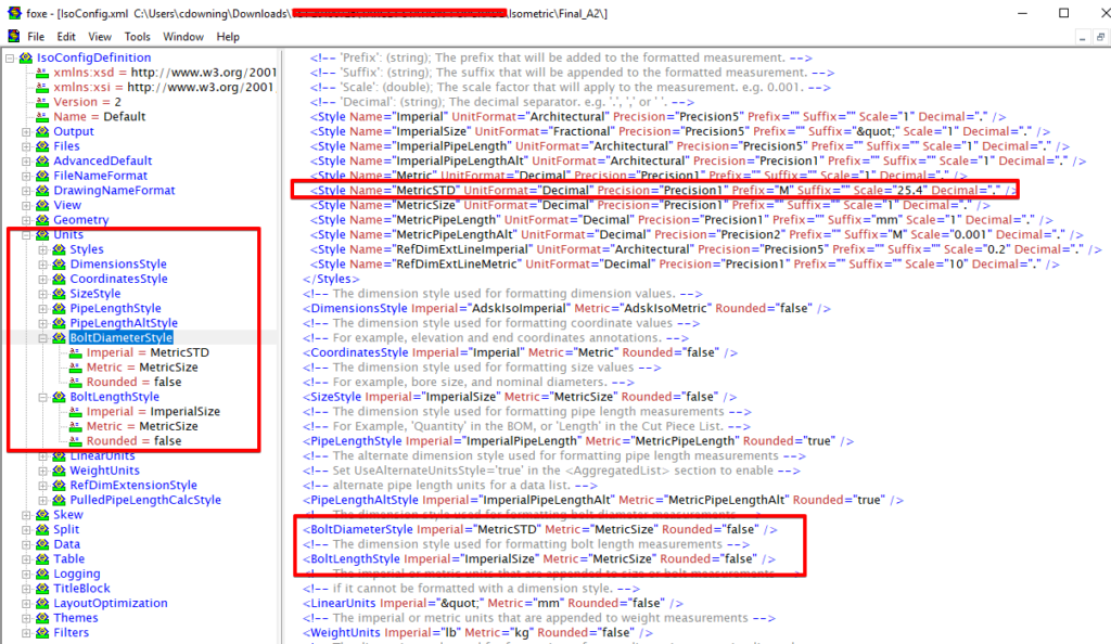
The example above shows the default style for the mixed metric project. First create a new style to use in the BoltDiameterStyle, in my example I have used the style name MetricSTD.
<Style Name=”MetricSTD” UnitFormat=”Decimal” Precision=”Precision1″ Prefix=”M” Suffix=”” Scale=”25.4″ Decimal=”.” />
<BoltDiameterStyle Imperial=”MetricSTD” Metric=”MetricSize” Rounded=”false” />
<BoltLengthStyle Imperial=”ImperialSize” Metric=”MetricSize” Rounded=”false” />
This should complete your Isometric configuration. All that is left is to test run an isometric using the newly configured style.
Still got Questions?
Book Training
With our Plant 3D training, you will learn how to use Autodesk Plant 3D and AutoCAD P&ID to complete a plant design project as well as common workflows used in plant design and how to solve validation issues.
Contact Us
We are here to ensure you receive a consistently high service and quality solutions for your business needs. We promise you won’t regret speaking to us, and if we can’t help you, we will try to find someone that can.