The Simulation Workspace in Fusion 360 is an incredibly powerful workspace. Giving us the ability to run a range of simulations on our designs to both assist in the design process and confirm our parts are designed to handle the work.
Fusion are continually adding functionality to the simulation workspace. So, this is an ever changing and expanding workspace which is great for Fusions future.
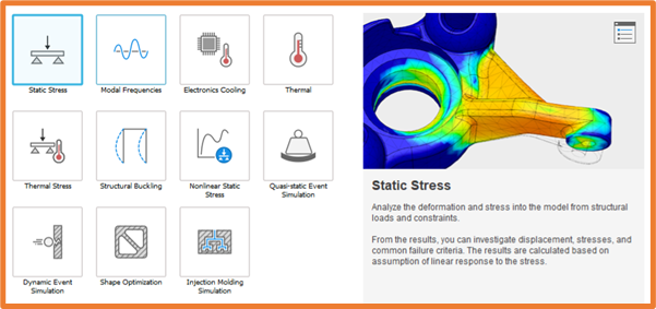
The simulation options range from Loads in Linear and Non-Linear Static Stress, Modal Stress and Structural Buckling. Thermal and Cooling in Electronics Cooling, Thermal and Thermal Stress. As well as Dynamic Event Simulation and Quasi-Static Event Simulation allowing the study of impacts, Shape Optimization giving us Ideal shapes, and Injection Moulding allowing us to optimize injection points and run cooling simulation.
Linear Static stress Analysis is available in every Fusion 360 subscription. All other simulation studies will require either cloud credits per study, or the Simulation Extension which gives unlimited studies. Allowing flexible access to studies in Fusion for one-off/infrequent studies. If you do have a more frequent need to run studies, the Simulation extension will be great for this application.
Below you will find more details on some of the study types available within Fusion 360.
Static Stress
Linear and Non-Linear Static Stress
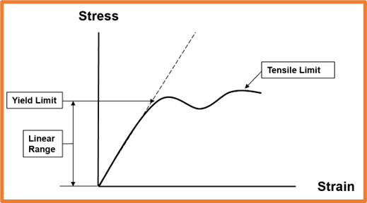
With Linear Static Stress we assume the results will be linear beyond the Yield strength of the material. In studies like this, if our component deforms beyond the yield strength or safety factor, we consider this a failure.
Non-Linear Static Stress will take into consideration the deformation beyond the Yield Strength, this is great for components that we expect to deform, and would like to control that deformation under certain loads.
Creating Studies
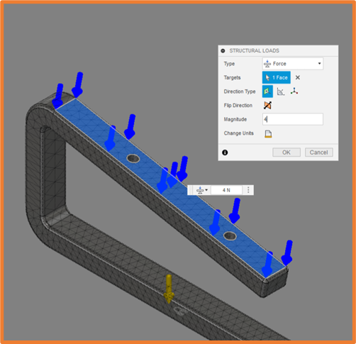
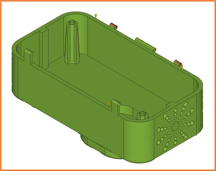
During Static Stress simulation we apply Loads, Constraints and Materials to our part. This is done to reflect the maximum loads and conditions our parts will need to withstand.
For the Loads, we can specify the surface the load acts on, and the direction this load is acting in.
Constraints will ensure certain components or faces have limited or no movement during the study.
For Materials, we can assign either the design material, or from a library of Fusion materials where the strengths of the materials have been pre-set. Otherwise, we can create our own materials for more custom studies.
Results
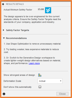
Once our study has completed, we are given the results within the Simulation Workspace, where Fusion provides us with recommendations based on the results. Below you can see our part has far exceeded the safety factor, so Fusion recommends running it through a shape optimization study to determine the optimal thickness. Otherwise, we can make our component thinner if we want to save on material and weight.
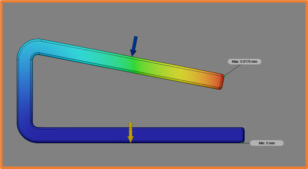
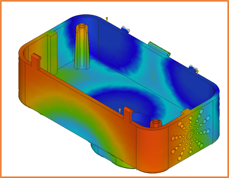
From the results view, we visualize the deformation of the component under the load applied. This shows us the areas of maximum and minimum displacement, as well as the gradient between the two values.
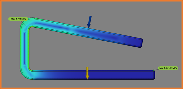
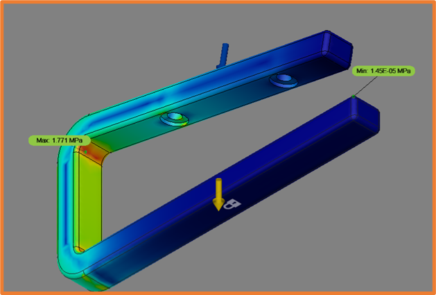
We can also see the stress that will be applied along our part, which allows us to establish which areas need further strengthening, if any. Again this will show us the areas with maximum and minimum stress.
Shape Optimization
With loads and an objective set for our existing component, we can run the Shape optimization study. This will help us understand where we can remove material, without compromising the functionality of the part.
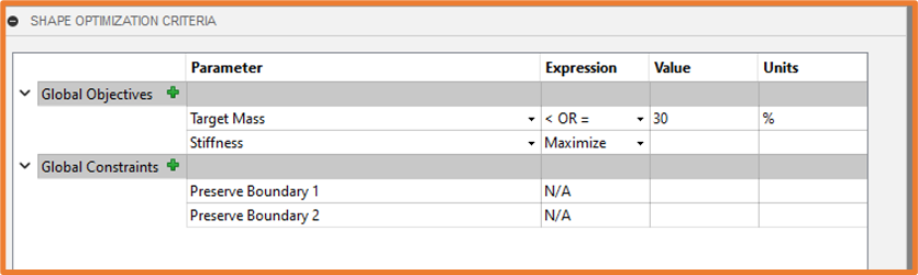
We can also set preserve areas, ensuring fixing points remain in place.
Injection Molding
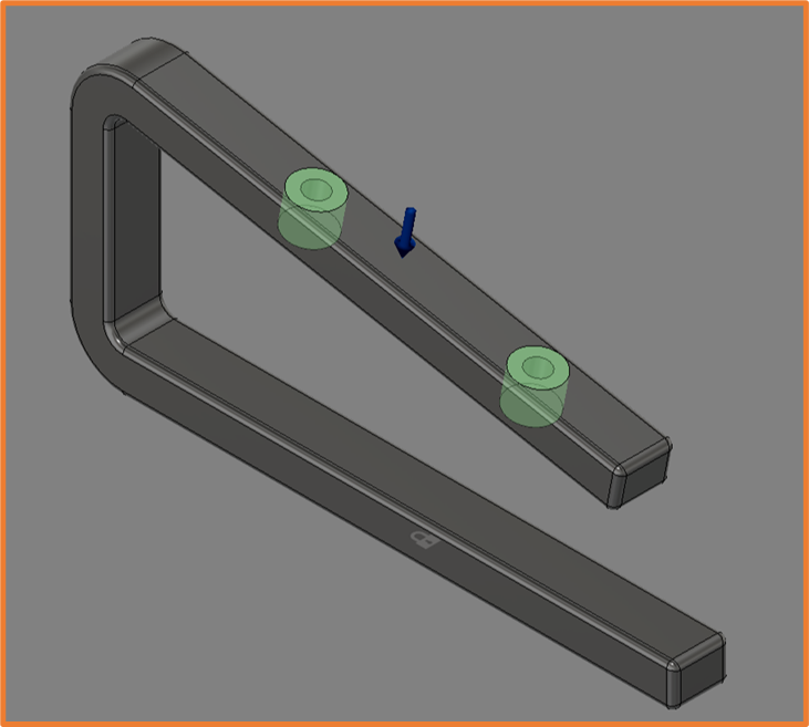
The injection molding simulation allows us to run studies based on the material, temperature and location of injection points. This gives us the ability to optimize the location of injection points and adjust our components for optimal manufacturing.
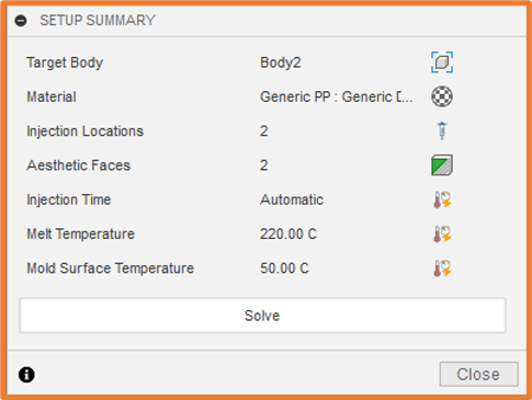
We can also set aesthetic faces, to ensure less cooling stress and warpage on certain surfaces.
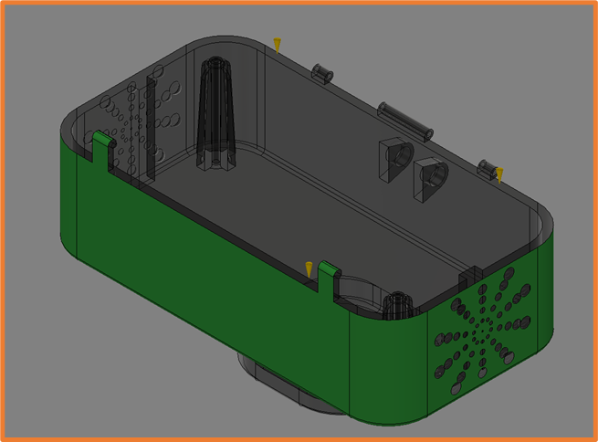
The results will give us an animation of the filling process and how the different feeds meet and interact, as well as Fill Times and Fill Confidence for the component.
Plastic Flow
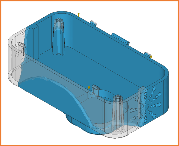
Fill Time
Fill Confidence
If you require further information regarding any of the simulation options, either covered in this article or not, please get in touch.
For more information on this blog post or if you have any other questions/requirements, please complete the below form: