


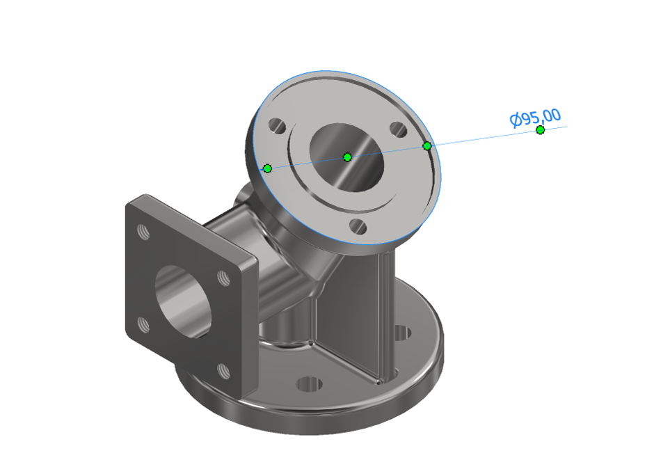
3D annotations in Autodesk Inventor are becoming a really handy way to keep design and manufacturing on the same page. Instead of juggling a model and a separate drawing, you can drop dimensions, tolerances, and notes straight onto the 3D geometry. It keeps everything in one place, makes your intent clearer, and honestly just cuts down on the back-and-forth that usually happens when a drawing gets misread or goes out of date.

How to Use 3D Notations
You’ll find all of Inventor’s 3D annotation tools inside the Annotate tab. Once you choose one of the dimensioning tools, Inventor will prompt you to select a dimensioning standard. In this example, we’re using ISO as our standard. After selecting it, the dimension tool becomes active and you can start picking edges, faces, or features directly on the model to place your 3D dimensions.
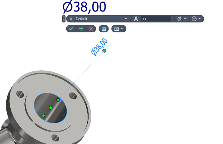
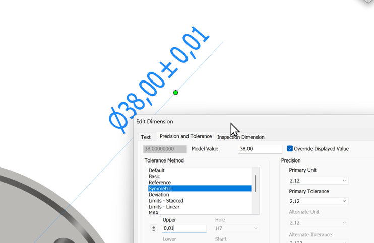
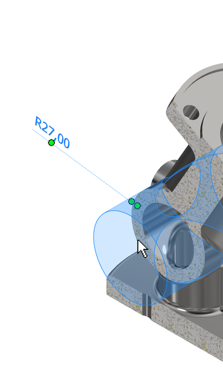
Using the dimension tool, you can select any hole, face or feature and Inventor will display the dimension directly in 3D. From there, you can drag and position the annotation anywhere in 3D space so it’s clear and easy to read. In the dimension’s sub-menu, Inventor also lets you apply preset tolerance types, making it simple to add the right manufacturing information without digging through extra settings.
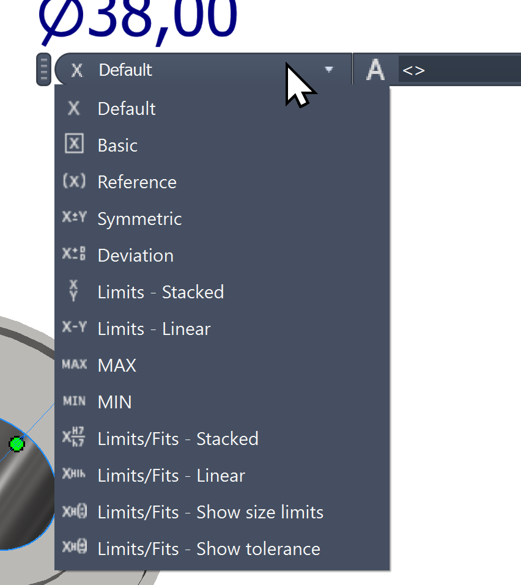
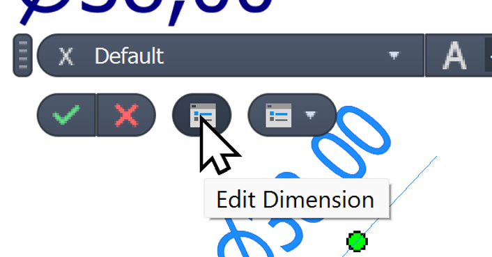
Using the edit dimension button we can then add our tolerance data into the annotation.
Promote Dimensions
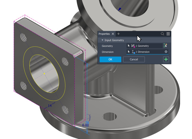
Promoting Dimensions lets you pull through the existing dimensions that were used to create a feature – whether they came from a sketch, an extrusion, or another modelling step. Once selected, Inventor brings those original driving dimensions forward and allows you to promote them directly into 3D annotations.
Hole and Thread
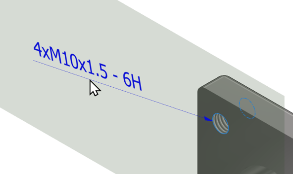
Hole and Thread automatically reads the hole features in your model and uses that information to generate accurate 3D hole and thread annotations. Instead of manually entering size or thread details, Inventor pulls everything straight from the feature itself.
Other Annotation Options
Inventor also gives us a set of quick-access annotation tools, making it easy to drop surface finishes, weld symbols, datums, GD&T frames, and general notes straight on the model without digging through menus.

- Surface Texture – Add surface finish symbols to show how smooth or rough a face needs to be.
- Welding Symbol – Place weld symbols directly on the model to communicate weld type, size and location.
- Datum Identifier – Mark key reference points or features that your tolerances will be based on.
- Datum Target – Define specific spots or areas used for measurement or inspection.
- Feature Control Frame – Add GD&T callouts to control form, orientation, position or runout.
- Leader Text – Simple leader notes for pointing out features or adding quick comments.
- General Note – Drop in any free-text notes that help explain requirements or intent.
Section View
We can use Inventor’s standard sectional tools to section through the part, and place an annotation on that plane.
Export Options
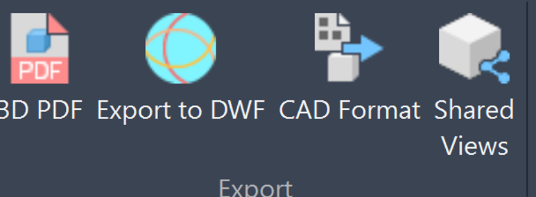
Autodesk Inventor gives us a few quick export options so we can share our models in whatever format works best for the team or the client.
- 3D PDF – Share a simple interactive 3D model anyone can view.
- DWF – Lightweight Autodesk-friendly file for quick reviews.
- CAD format – Export to STEP/IGES etc for other CAD systems.
- Shared Views – Create an online view for easy cloud-based feedback.
Using Your Annotation in Drawings
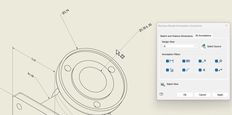
Once we’re in the drawing environment, we can bring our 3D annotations straight through without re-dimensioning anything. Simply right-click on your view and choose Retrieve Model Annotations to pull in all the 3D dimensions, notes and tolerances already defined in the model.
Still got Questions?
Book Training
Our range of Autodesk Inventor training courses will teach you how to create production-ready parts and assemblies through hands-on learning experience. Make sure you contact us to find out which course is best for you.
Contact Us
We are here to ensure you receive a consistently high service and quality solutions for your business needs. We promise you won’t regret speaking to us, and if we can’t help you, we will try to find someone that can.