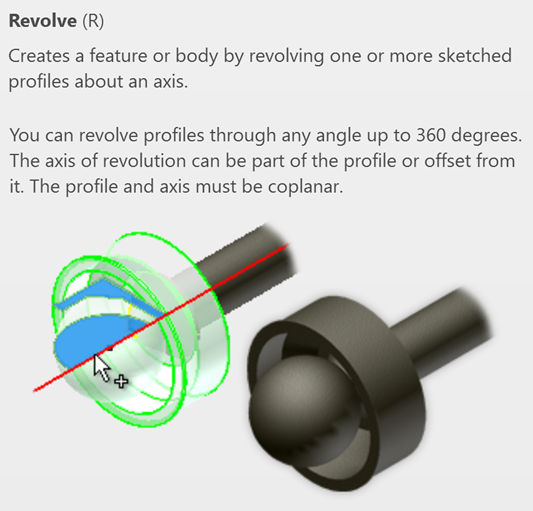
In the world of 3D CAD modelling, creating perfectly symmetrical parts is a common requirement. Components such as bottles, pulleys, shafts, bowls, wheels, and pipes often share one key characteristic; they are based on rotational geometry. This is where the Revolve tool in Autodesk Inventor becomes incredibly powerful.
The Revolve feature allows users to create 3D solid or surface models by rotating a 2D sketch profiles around an axis. Instead of building complex shapes using multiple extrusions and cuts, the Revolve tool can generate smooth, accurate geometry in just a few clicks.
The Revolve command is ideal for creating:
- Cylindrical parts
- Cones
- Hollow containers
- Mechanical shafts
- Rings and washers
- Symmetrical industrial components
Using Revolve offers several advantages:
- Faster modelling.
- Complex round parts can be created with a single feature.
- Better accuracy.
- Rotational geometry is mathematically precise.
- Cleaner feature tree.
- Instead of multiple extrusions, one revolve operations keeps models organised.
- Easier editing.
- Updating the sketch automatically updates the entire revolved components.
Let’s explore a simple example!
- Starts a new part file (standard metric ipt) and create geometry based on the below example.
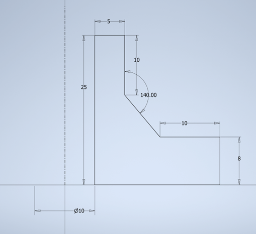
- Create a 2D sketch by clicking Start 2D Sketch.
- Choose a plane: XY plane.
- Draw the profile of your object using: Line.
Important Tip: Only draw half of the object project in most cases. The revolve operation will generate the full geometry.
- Add a centreline (Axis). The Revolve operation need an axis of rotation:
- Select the Centreline tool.
- Draw a vertical or horizontal construction line.
- This line becomes the rotation axis.
Without an axis, the Revolve command will not work properly. you can use a centreline or the default axis if drawn around these defaults.
- Finish the Sketch – click Finish Sketch after completing the profile and centreline.
- Launch the Revolve command.
- Go to the 3D model tab.
- Click Revolve and the Revolve dialog box will appear.

Understanding the Revolve Selections
The Revolve command requires two main selection:
- Profile: Select the closed sketch profile you want to rotate.
- Axis: Select the centreline or model edge that acts as the rotation axis.
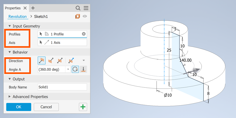
Setting the Revolve Angle
The angle determines how far the sketch rotates. Revolve Output Options:
- Solid: Creates a solid 3D body.
- Surface: Creates only a surface without thickness.
Key tips to remember:
- Apply geometric constraints to stabilise sketches.
- Fully dimension sketched – well defined sketches reduce errors later.
- Keep sketches simple – avoid unnecessary lines and details.
- Use construction geometry.
- Construction lines help create accurate revolves axes.
The Revolve tool in Autodesk Inventor is one of the most efficient features for creating rotational parts quickly and accurately. Once you understand the relationship between the sketch profiles and the axis rotation, you can build sophisticates 3D models with minimal effort.
For beginners, mastering Revolve is an important step toward becoming proficient in parametric CAD modelling. Whether you’re designing machine components or consumer products, this tool will significantly improve your workflows and modelling speed.
Start with simple shapes, experiment with different profiles, and gradually move toward more advanced designs. With practice, the Revolve tool will become an essential part of your Autodesk Inventor toolkit.
Still got Questions?
Book Training
Our range of Autodesk Inventor training courses will teach you how to create production-ready parts and assemblies through hands-on learning experience. Make sure you contact us to find out which course is best for you.
Contact Us
We are here to ensure you receive a consistently high service and quality solutions for your business needs. We promise you won’t regret speaking to us, and if we can’t help you, we will try to find someone that can.