
Creating accurate and editable structural frames is essential. Autodesk Inventor 2026 continues to make this task efficient with its powerful Frame Generator environment, a dedicated toolset for designing skeletal and structural frames using standard profiles.
This blog introduces the Frame Generator in Autodesk Inventor 2026, explains how it works, and highlights why it is an indispensable feature for designers and engineers.
What is Frame Generator in Autodesk Inventor?
Frame Generator is a specialised design environment within Autodesk Inventor used to create 3D structural frames based on an underlying skeleton model. Instead of modelling beams and members manually, Frame Generator allows you to place industry-standard profiles such as angles, channels, tubes and I-beams, along sketch or model edges. These members are fully parametric, associative, and compliant with common structural standards.
Key Features of Frame Generator in Inventor 2026
- Standard Structural Profiles. Inventor 2026 includes extensive libraries of profiles such as:
- ISO, ANSI, DIN, JIS, and GB standards
- Square, Rectangular, round tubes
- C-channels, L-angles, I-beams, T-sections
- Custom profiles can also be created and saved for reuse.
- Skeleton-Based Design. Frame Generator works best with a skeleton model:
- 2D sketches
- 3D sketches
- Existing part or assembly edges
- Any changes to the skeleton automatically updates the frame members, ensuring design flexibility.
- Automatic Member Placement. With just a few clicks, you can:
- Select sketch lines or edges
- Assign profiles
- Control orientation, alignment, and offsets
- Inventor handles the creation of individual frame members as separate parts within the assembly.
- Intelligent Trimming and Notching. Frame Generator provides tools to:
- Trim members to each other
- Create miter joints
- Apply cope cuts and notches
- These tools help produce fabrication-ready frames with accurate intersections.
- Parametric and Associative Design. All frame members remain associative to:
- The skeleton sketch
- Assembly constraints
- Design changes
- This ensure quick design iterations without rebuilding the structure.
- BOM and Documentation Support. Each frame member:
- Appears automatically in the Bill of Materials (BOM)
- Can be labelled with part numbers, materials and lengths
- Is fully supported in Inventor drawings
- This simplifies manufacturing documentation and cost estimation.
Let’s dive into creating a basic frame!
1 – Start a new standard mm ipt.
2 – Create a Skeleton Model, use 2D (or 3D) sketches to define the frame layout.
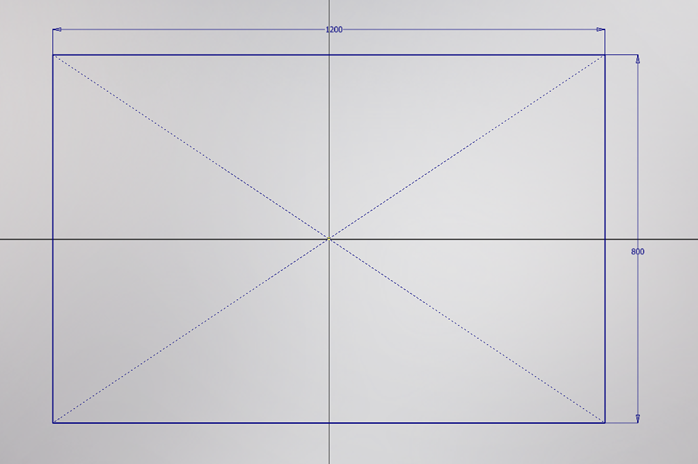
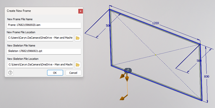
- Sketch 1 – as example below: Rectangle 1200mm x 800mm
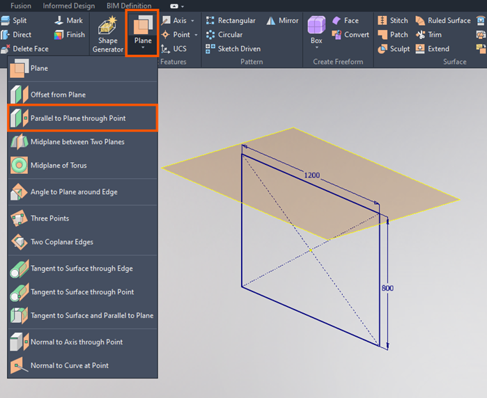
- Sketch 2 – create a work plane parallel to plane through point. Select this plane for Sketch 2.
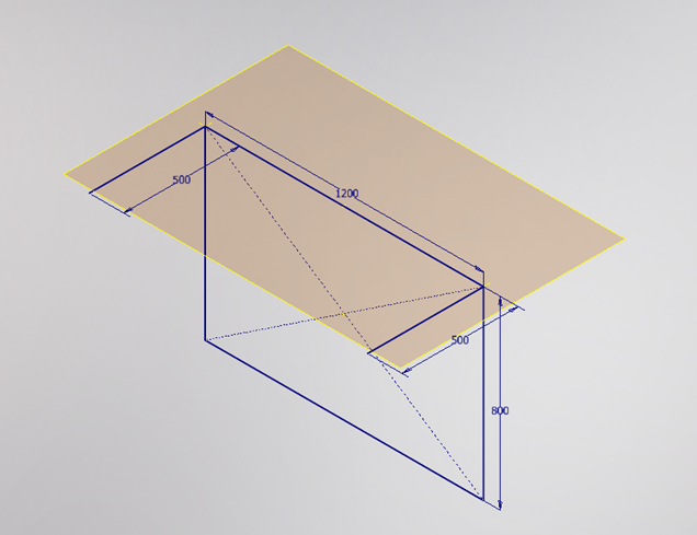
- Place lines (500mm) as in example below and Finish Sketch.
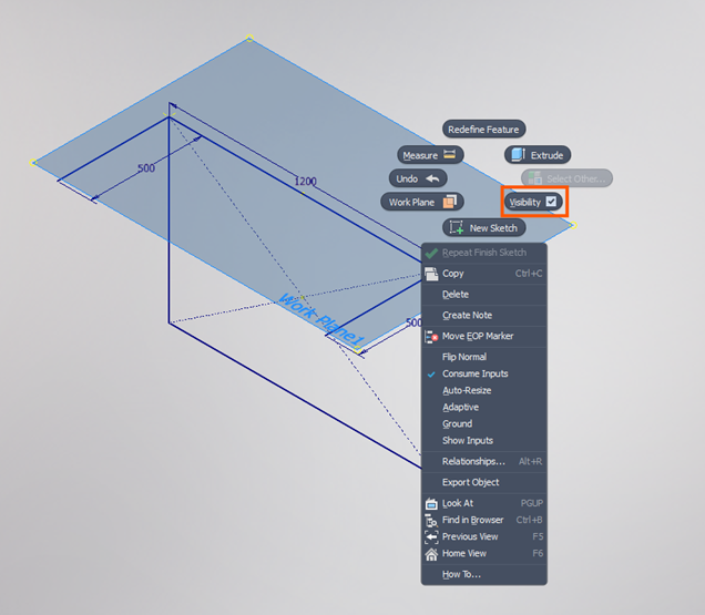
- Right click on the work plane and toggle the visibility off (cleaner when we bring this into an assembly). Save the part (Frame Skeleton example).
3 – Create a new standard mm iam. Place the Frame Skeleton Example part in the assembly. Save the iam (Introduction to Frame Generator).
4 – Enter Frame Generator environment and go to Design tab > Frame panel.
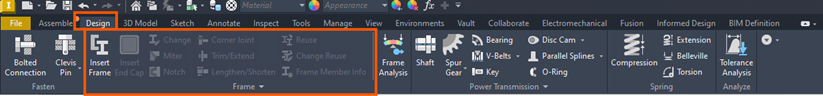
5 – Select Insert Frame.
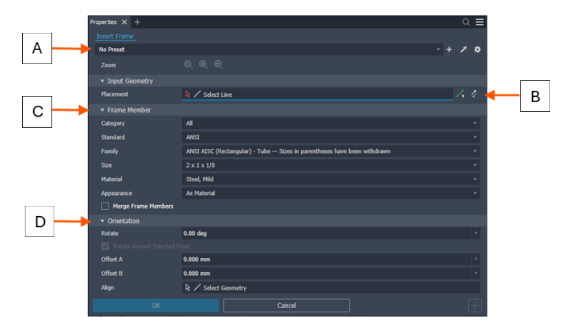
A – Optionally
Select Copy properties & select a member to match properties & orientation
Select a saved Preset to configure the Frame Member.
Expand the Advanced Settings Menu in the upper right corner of the panel
B – Placement/Points Selection


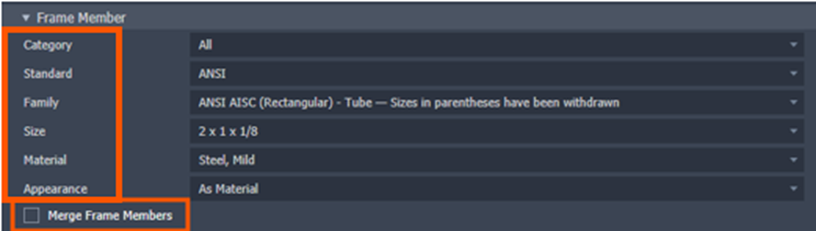
C – Frame Member from Existing Inventor Library.
Select each drop down to explore your options; Category, Standard, Family, Size, Material, Appearance.
Merge Frame Member – Optionally, check Merge Frame Members to select multiple edges and merge them into one frame member. Note: Merge Frame Members is not available for members places with point selection.
D – Orientation
Specify the orientation. Select a radio button in the display to position the frame member.
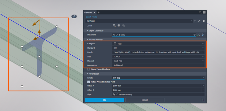
6 – Select all the lines from Sketch 1 (the rectangle 1200mm x 800mm) and select the options as per the below image. Then select OK.
7 – A Create New Frame dialog box will appear which creates and saves the frame assembly in the browser hierarchy. All frame solving occurs under the frame assembly. Select OK.
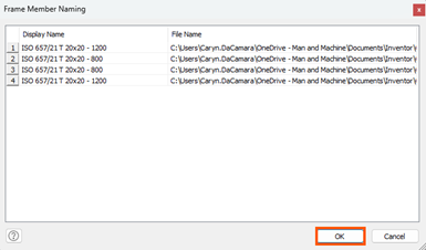
8 – Select OK again.
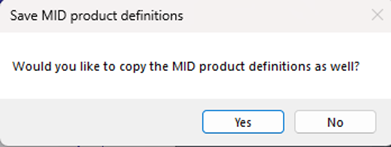
9 – Optional: These definitions enable the configuration and generation of product variants, along with their associated output types (such as Revit families, drawings, or Bill of Materials), based on a predefined set of parameters and rules.
10 – Add additional frames to Sketch 2.
Key Benefits of Using Frame Generator:
- Faster frame design compared to manual modelling.
- Easy design changes and updates.
- Accurate, standards-based profiles.
- Automatic BOM and cut-length data.
- Fabrication-ready models.
And that is how to create frames in the Autodesk Inventor Frame Generator tool. At this point, you can Trim and Adjust, apply functionality such as miter, trim and notch tools, finalise and document as well as generate drawings, BOMs and cut lists.
The Frame Generator in Autodesk Inventor 2026 is a powerful tool for creating robust, parametric structural designs with speed and accuracy. By leveraging skeleton modelling, standard profiles, and intelligent trimming tools, designers can focus more on functionality and less on repetitive modelling tasks.
Whether you’re designing a simple support frame or a complex industrial structure, Frame Generator helps transform concepts into production ready models efficiently.
Still got Questions?
Book Training
Our range of Autodesk Inventor training courses will teach you how to create production-ready parts and assemblies through hands-on learning experience. Make sure you contact us to find out which course is best for you.
Contact Us
We are here to ensure you receive a consistently high service and quality solutions for your business needs. We promise you won’t regret speaking to us, and if we can’t help you, we will try to find someone that can.