

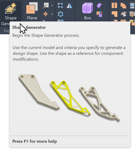
Autodesk Inventor’s Shape Generator gives you a powerful way to explore lighter, stronger and more efficient design options, without the trial and error of traditional modelling. By defining loads, constraints and target mass, Shape Generator produces optimised geometry that highlights where material is needed and where it can be removed. It’s an intuitive entry point into generative design thinking, helping you create parts that perform better whilst reducing weight, cost and manufacturing waste.
Adding Constraints
In the Analysis tab, you can apply constraints to your model through the Constraints panel. You can also right-click the Constraints node in the model browser to choose the type you need.
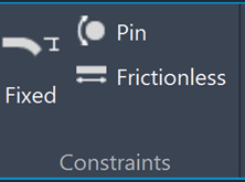
Common Constraint Types:
- Fixed: Locks a selected face, edge or vertex in place by removing all degrees of freedom.
- Pin: Ideal for cylindrical surfaces, allowing you to control radial, axial or tangential movement or deformation.
- Frictionless: Used on flat or cylindrical surfaces to prevent movement or deformation in the direction normal to the surface, while still allowing sliding or rotation.
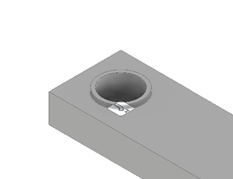
Image showing fixed constraint on hole diameter.
Applying Forces and Loads
To generate an accurate optimised shape, Shape Generator needs realistic loading conditions that reflect how the part will be used. You can apply a variety of load types – including Force, Pressure, Bearing, Moment, Gravity, Remote Force, and Body Loads – to simulate the real-world forces acting on your model. These inputs guide the solver, helping it remove material where it isn’t needed and reinforce areas that carry the most stress.
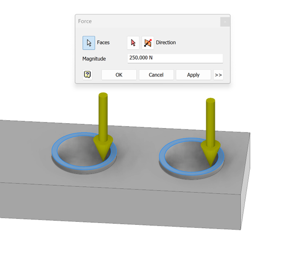
Image showing force on two pin locations.
Preserving Regions in Shape Generator
In many designs, certain areas must remain untouched during optimisation, such as bolt holes, mounting pads, or other critical interfaces. Preserving these regions ensures the final Shape Generator result still fits, assembles and functions exactly as intended.
How to preserve an area on the model:
To protect a region, select the faces or features you want to keep and apply a Preserve Region constraint from the Shape Generator toolbar. Inventor will treat these areas as fixed geometry, maintaining their size and shape whilst optimising the surrounding material. This gives you a lightweight, efficient design without compromising essential connection points.
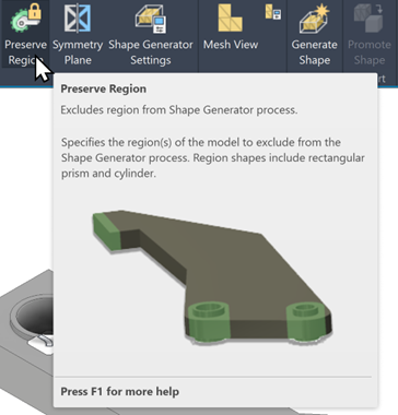
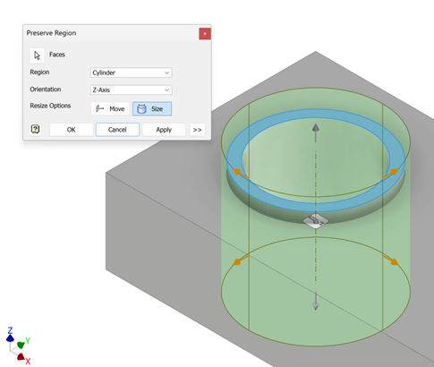
You can also adjust preserved regions directly from the Preserve menu – switching the shape type from cylinder to box, redefining the selected area, or resizing and repositioning the preserved region to better match your design requirements.
Shape Generator Settings
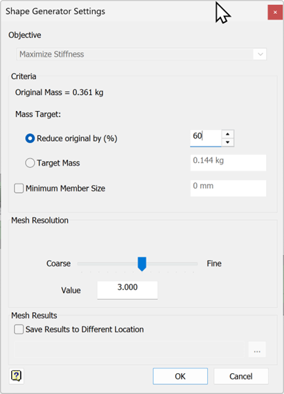
The Shape Generator settings let you define the design criteria that guide how Inventor optimises your model.
- Mass Reduction: You can specify a percentage of mass to remove or set a target mass for the final design. This helps Shape Generator focus on lightweighting while maintaining structural performance.
- Member Size Constraints: These settings define the minimum member size allowed in the mesh. They ensure that walls, ribs and structural features remain manufacturable and strong enough for real-world use.
- Mesh Resolution: You can adjust the resolution slider or enter a numerical value to control mesh quality. High resolution produces a smoother, more detailed mesh but increases processing time.
Together, these settings let you fine-tune the optimisation process, balancing strength, manufacturability, and performance to achieve a practical, efficient design.
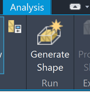
Once your analysis setup is complete, select Generate Shape to open the Shape Generator dialog, then choose Run to begin the optimisation. When the process finishes, Inventor provides a recommended 3D mesh that highlights where material should be kept or removed. This mesh acts as a guide for refining your final design, helping you create lighter, stronger and more efficient parts while still meeting all functional and constraint requirements.
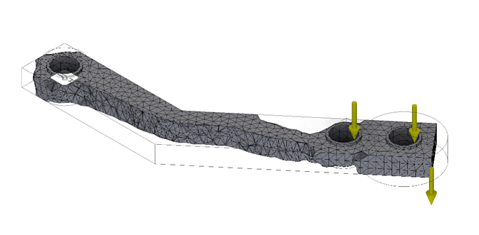
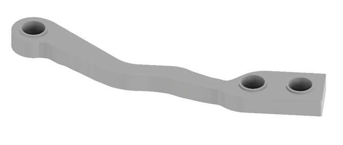
Finished shape after frame generator.
Once the 3D mesh has been generated, you can promote it into the modelling environment to use as a reference for refining your final geometry. From the Export panel, select Promote Shape, then choose whether to bring the mesh directly into the current part file or export it as an STL for use in another workflow. This gives you a clear visual guide for sculpting a manufacturable, optimised design.
Still got Questions?
Book Training
Our range of Autodesk Inventor training courses will teach you how to create production-ready parts and assemblies through hands-on learning experience. Make sure you contact us to find out which course is best for you.
Contact Us
We are here to ensure you receive a consistently high service and quality solutions for your business needs. We promise you won’t regret speaking to us, and if we can’t help you, we will try to find someone that can.