Many of you will be familiar with Fusion 360’s Manufacturing workspace and its ability to push out scripts for CNC machining, or Subtractive Machining. Fusion also has the functionality for Additive Manufacturing or 3D Printing, and in this article, we are going to explore a quick overview of the extension as well as basic tips for getting the best results.
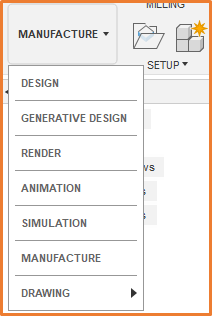
To get started we will need to head over to the Manufacturing workspace, if you are not there already. This can be done by clicking on the dropdown menu in the top left of the interface, which generally shows “Design” or the name of the workspace currently active, from here select Manufacture.
Once in the Manufacture workspace, you will see a few tabs available in the ribbon, including Milling, Turning and Additive. We will be working with the Additive tools; once selected you should see the ribbon as below.
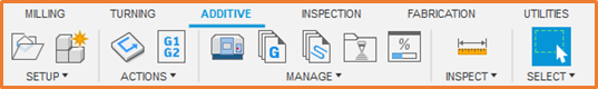
Note Fusion is continually updating and evolving their interface so your icons may look slightly different, but you should still have them in the same order.
As with any of the workspaces in Fusion, the interface is designed to work from left to right. So long as you work your way through each tool from left to right on your way to your export, you will have all the required information. We will therefore look at all the tools in this order.
Setup
Our first stop brings us to Setup, as you can guess this includes all the options for your environment including the Machine, Arrangement, and the Model selection.
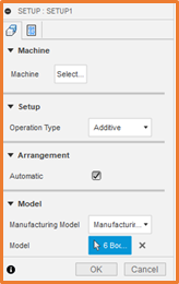
Machine allows you to select the machine you will be using for the printing; you can choose from a wide range of vendors within your own custom database or using the Fusion 360 library.
Setup lets you change between the different machining types. Your workspace can include setups for Additive, Subtractive, Inspection and Milling/Turning.
Arrangement can either be manual where you would like to place your model, or Automatic if you want fusion do this for you.
Model is where you choose which parts are included in setup. If you want to change the geometry or any features on the model you may want to run through the Create Manufacturing Model process, then come back to this point.
Post Process will be where you enter a program name and comments for output.
Create Manufacturing Model creates a new version of your model within the file, where you can make edits to the geometry or add and remove bodies without it affecting your main model. If you do create a new Manufacturing model you will need to ensure that you change the reference model in the Setup.
Once you chose the machine and model, you should have a few more contextual options available to you within the ribbon, these are broken down into the following categories: Position, Print Settings, Infill and Supports.
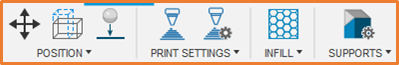
Position includes the various options for moving the part within the desired printing platform. You can also place the item directly onto the platform so that there are no gaps if you desire. Minimize build height will ensure that your model is rotated into an optimal position for minimizing the final height of your print.
Print Settings enable you to switch between or adjust any of the settings for the printing. This is generally limited by the machine you have chosen; we recommend leaving this with the defaults wherever possible.
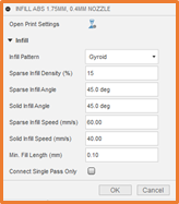
Infill lets you choose the pattern, density, angle, and length of the infill. This can save a lot of material and make your models lighter too. It is a great addition that can automatically calculate all the required parameters.
Note that this will change the strength of your part, if it already has a lower safety factor this is only recommended for prototyping.
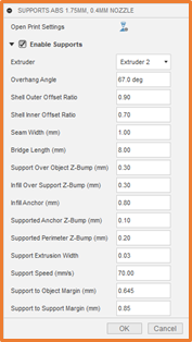
As your model gets printed, there may be some items with an overhang far too wide to print it. Automatic supports allow the print to include some valuable support structures, which can be removed afterwards and keeps your model intact during the printing process.
Actions
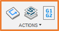
From here we move onto the actions panel. If you have not made any changes to your setup, you can jump straight to Simulate. Otherwise it may be worth running the Generate where the toolpath will be regenerated after any changes.
Within the simulation interface you can preview the printing process. This allows you to watch the entire sequence that will be used to print your part. The controls for the animation are situated at the bottom of the screen. These buttons are mirrored on either side of the Play/Pause button, Next Move, Next Operation, and Go to End. Just below that is a slide which controls the speed of the simulation.

You will also see a window displaying information about the toolpath including the current height, current time, and layer count.
Finally, once you are happy with the simulation and the print setup you can proceed to the Post Process this is where you will push out the NC file which your printer needs. Here you will find most of the settings you have already entered and need to confirm as well as a few extra details you may need to add.
Configuration Folder is where your setup file will be saved to or loaded from.
Output Folder is where you post will be saved, you can also set the NC extension here.
For more information on this blog post or if you have any other questions/requirements, please complete the below form: