
How to export an Inventor model giving it maximum functionality within Plant 3D
Introduction
Autodesk Inventor is a great tool for any mechanical design project and with the Tube and Pipe environment it is also very good at doing small plant skids and plant rooms. For large scale plant factories and the like, it is hugely beneficial to utilise a product such as AutoCAD Plant 3D. However, Plant 3D is not so good for showing high level fabrication details within that larger scale design. It is aimed at creating accurate 3D models that will provide detailed reports such as cut lists, valve list, pipeline lists and pipeline drawing isometrics .
Therefore, a combination of both products within the Product Design and Manufacturing package could be the solution you require to meet all your Plant Design needs. Autodesk understands these needs and as with most products, they have come up with solutions on how to seamlessly transition between one product and another.
Document Settings
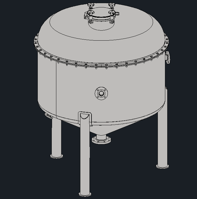
First, we need a completed model in Inventor, as shown below. We need to decide how many iterations of this model we wish to include in our Plant 3D model. Each iteration is a duplication of the amount of data; therefore, we may need to simplify the Inventor model removing a lot of the unnecessary design data and details which are not required in the large-scale Plant 3D model, in layman’s terms, the simpler the model and smaller the file size, the better.
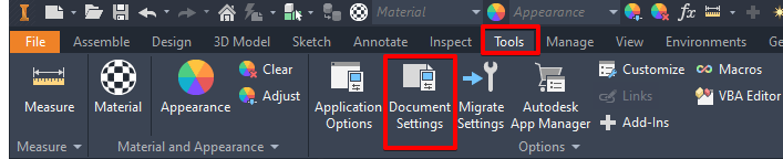
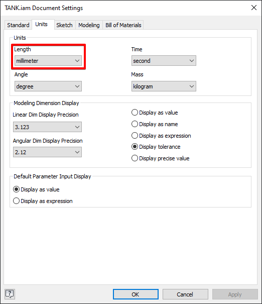
First you must make sure that your model units will match the units of your Plant 3D project, either inches or millimeters. The images below show how you can adjust the model units if required.
Model Export Preperation
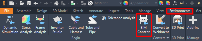
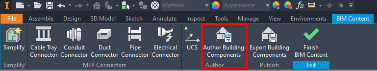
The next stage is to configure the model so that it exports with added information and functionality. Activate the Environments tab and select the BIM Content command as shown below. Once activated you are able to specify what type of model it is and also the type of connections it has, if any.
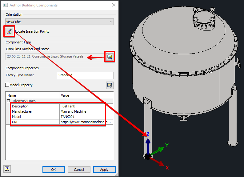
Activate the Author Building Components command shown above to add the required data to the model. First create a work point that you will utilise as the origin of your Inventor model. This will be the insertion point connected to the cursor when you place your Inventor model into the Plant 3D model. It’s important to pick the most logical point relevant to your model, in my example below I have used the centre point on one of the 3 legs supporting the tank. You may wish to choose a centre point of a nozzle on a lot of assemblies such as valves.
If possible, specify an OmniClass Number and Name from the list of available classes on the browse button, give the Family Type Name if required and finally add the values in the Identity Data. This prepares your model so that it exports with tangible data for use in either Plant 3D or other products such as Revit.
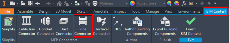
I used the Pipe Connector command on the tank nozzles to specify what type of pipe connection the nozzles require.
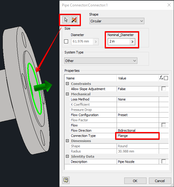
Add your pipe connectors and any other connectors as needed. I have added my Nominal Diameter in inches in this model as that is how the pipe spec has been configured for my Plant 3D project.
Shrink-Wrap & Export Model
As mentioned before, we want the model to be as simple as possible for the Plant 3D project. Use the Shrink-wrap tool to remove all parts and features that are not required for the Plant 3D model. For the design intent of my Plant 3D project, I only require the outer perimeter of the tank and the distance between nozzles. An example of the settings I have configured for my shrink-wrap are shown below.
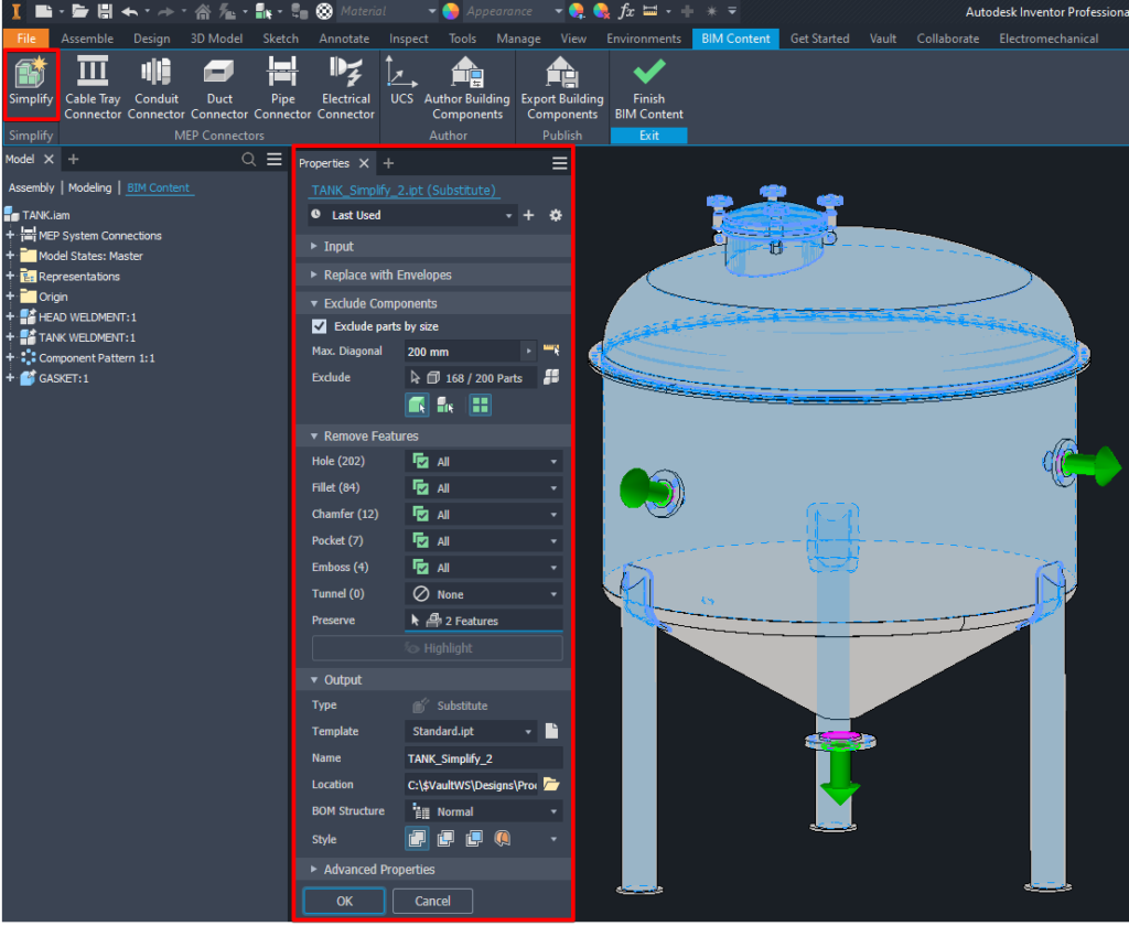
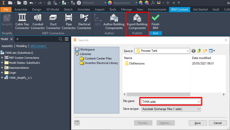
Once the shrink-wrap is complete you can export the new simplified model to ADSK format.
Import Into Plant 3D Model
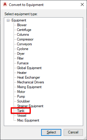
The ADSK file can be directly added to the Plant 3D model. On the Home tab, Equipment panel, select the Convert Inventor Equipment command to browse to and import the simplified ADSK file. Select what type of equipment your model is.
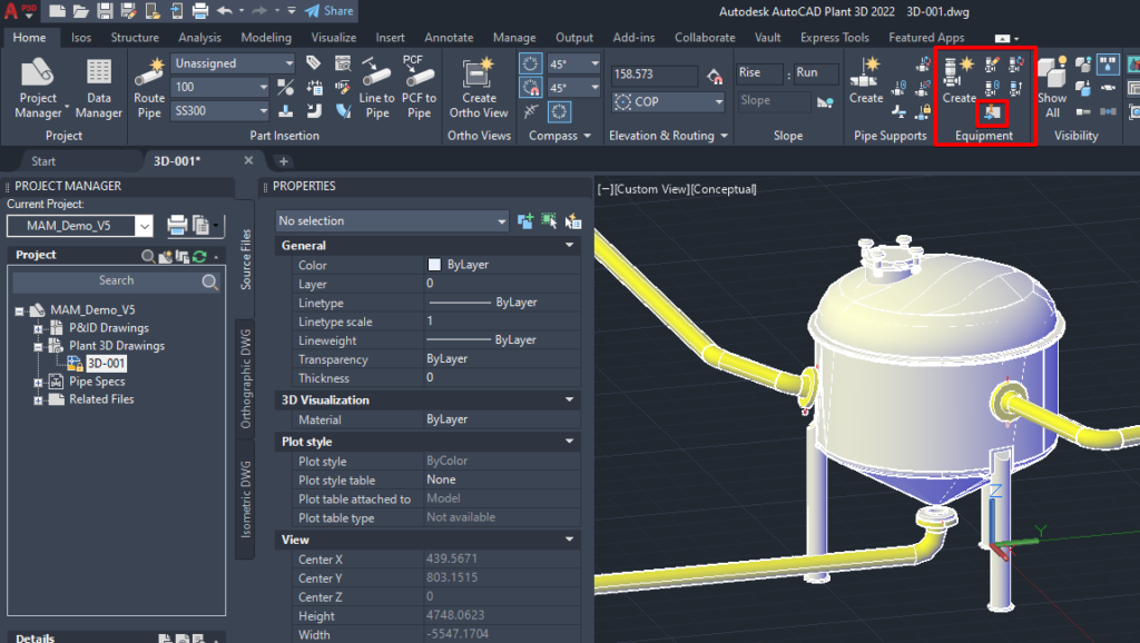
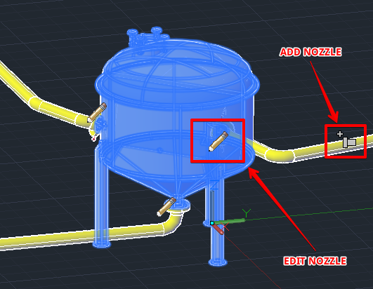
You can connect your pipe directly to the nozzles configured in the Inventor model or you can edit and even add more nozzles using the different icons on the model.
Voila, we have an Inventor model seamlessly added for use within our larger scale Plant 3D project. We can pipe to and from this model in exactly same way as we would with any out-of-the-box Plant 3D equipment model template.
Hopefully you found this blog useful and informative. If you have any questions please do not hesitate to contact Man and Machine.
Happy Planting!!!
Still got Questions?
Book Training
Our range of Autodesk Inventor training courses will teach you how to create production-ready parts and assemblies through hands-on learning experience. Make sure you contact us to find out which course is best for you.
Contact Us
We are here to ensure you receive a consistently high service and quality solutions for your business needs. We promise you won’t regret speaking to us, and if we can’t help you, we will try to find someone that can.