


In this blog, we’ll be focussing on AutoCAD Mechanical and the extensive range of functionality it provides. Typically, I’m an avid Autodesk Inventor user, so switching over to Mechanical, it’s great to see the range of functionality and intelligent objects it has to offer.
Automatic Layer Management
First, an amazing feature is automatic layer management. We all know that managing layers in AutoCAD can sometimes be a tedious process. AutoCAD Mechanical helps simplify this with an automatic layer management system, assigning entities to predefined mechanical layers when using Mechanical commands, regardless of which layer is currently active.
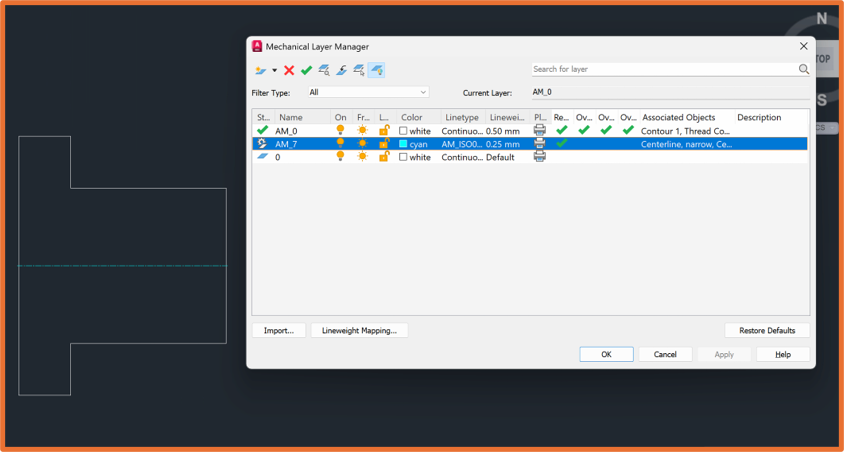
For example, I’ve created a quick drawing and used the AMCENTLINE command. You’ll notice that the centreline appears in a different colour, indicating that it sits on a different layer. This happened automatically as soon as the centreline was placed.
Let’s head into the Mechanical Layer Manager using the AMLAYER command. Like AutoCAD’s Layer Manager, this displays the layers within our drawing, including the automatic layers controlled by Mechanical. These can be easily identified by the gear icon shown under Status.
Here’s where it gets interesting. If we decide to rename the centreline layer, any new centrelines we create will continue to be automatically assigned to it. Neat, right?
And this functionality isn’t limited to centrelines. Automatic layer management also extends to other Mechanical entities, including construction and hidden lines, text and hatching, symbols and notes, as well as title blocks and borders.
Automatic Dimensions
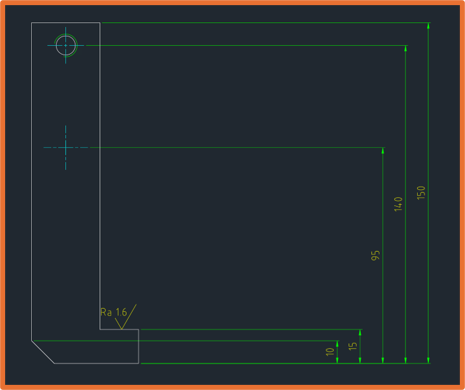
Another powerful command is AMAUTODIM, which allows us to create multiple automatic dimensions, such as Parallel, Ordinate or Shaft/Symmetric, in a single step. This helps reduce the repetitive process of adding dimensions manually.
Simply enter the command or select Multiple Dimensions from the Dimension section under the Annotate tab. Choose your preferred settings within the dialog box and select OK. From here, specify your starting point, followed by the extension line where your dimensions will align.
This next feature is one of my favourites when working with Mechanical dimensions. If a dimension is adjusted or deleted, the remaining dimensions automatically reorganise themselves to eliminate any gaps, saving time while keeping our drawing neat and tidy.
Content Libraries
Within AutoCAD Mechanical, we can access Content Libraries to quickly place standard parts and features without needing to draw them manually. AutoCAD Mechanical includes over 700,000 standard parts and features, covering standards such as ISO, ANSI, DIN, JIS, BSI, CSN and GB. If you work with custom parts, these can also be created and saved to a content library.
Within the ribbon, head to the Content tab, where we can quickly access commonly used standard parts. Alternatively, select Content Libraries to browse the wider range of available content. Better still, Mechanical doesn’t limit us to inserting individual parts and features. We can even create entire screw assemblies in one go.
Let’s create a quick screw assembly. Within the Content tab, head to Screw Connection under the Fasteners section. From here, a dialog will appear where we can select the individual parts we want to include within our assembly.
Upon selecting our first component, Mechanical displays the available sizes for that part. As we continue adding components, our available options may become more restricted depending on the combination of parts selected.
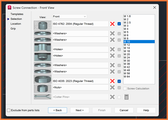
Once happy with our selection, hit Next to place the start point, followed by the endpoint. Mechanical will calculate the length of the bolt and draws the screw connection. Once placed, we can always edit by double clicking the screw connection and modify as before.
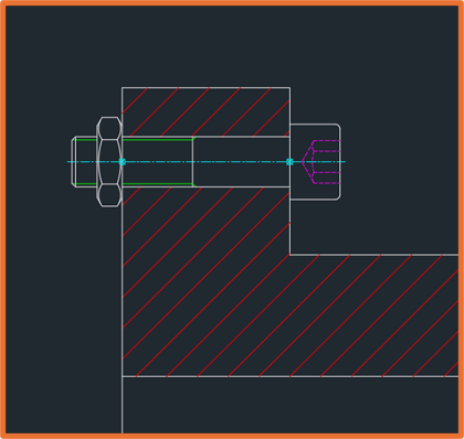
When we wish to remove the screw connection, or any standard part, AutoCAD Mechanical comes with another quick and powerful command called AMPOWERERASE – a command that’s worth the learning! Unlike the standard erase tool within AutoCAD, this tool knows which components are mechanical objects, therefore can clean and heal the surrounding environment when removing.
Views
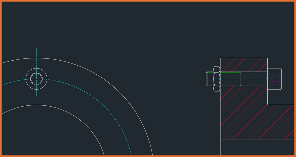
Following on from creating a standard part, we’ll now look at AMPOWERVIEW, found within the Content tab under Tools. This command allows us to quickly generate a top or bottom view from an existing side view, or vice versa, saving us from having to redraw the component manually.
After starting the command, select the standard part you want to create a new view from. A dialog box will appear, allowing you to choose the required view. Once selected, simply click where you want to place the new view within your drawing.
The next command we can use is AMPOWERCOPY. It’s important we use the Mechanical copy command against mechanical entities as this brings over the mechanical intelligence and associated data.
BOM and Part List
Once we’re ready to start annotating, we can make use of Mechanical’s Balloon and Parts List features. First, we may need to add some part references to our geometry, which can be found within the Annotate tab under the BOM section.
Part Reference (AMPARTREF) allows us to identify geometry and add relevant information to it, providing a crucial first step when creating our parts list. You may notice that some part references already exist within the drawing. These belong to standard parts and are automatically created and populated when the parts are placed into the drawing.
Next, we need to generate our BOM, which acts as a database for all the part references within our drawing. Select the BOM button (AMBOM) and AutoCAD Mechanical will scan the drawing for any part references, collecting them together within the BOM table.
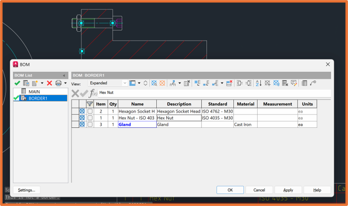
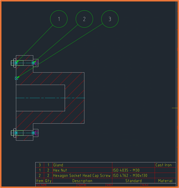
Now we have a BOM, we can add the balloons. Within the Annotate tab, select the Balloons function (AMBALLON) followed by autoALL, or type a. Our selection tool is now restricted to part references only. Select all you wish to balloon (enduring you don’t create repeated balloons), followed by enter, placing in a suitable location.
Once your balloons are placed, we can add the parts list – the order can be amended later. Select the Parts List command within the Sheet section (AMPARTLIST) and a dialog will pop up with a table. This table is derived from the one you’ve seen and created in the BOM, changes made here effect the BOM as well as the part list, and vice versa – therefore you can edit either within the Part List or BOM. Select OK to place the part list within your drawing. Should you need to edit the Part List, double click the table.
Finally, we can re-arrange the balloon order. Within the Balloon section, select the balloon renumber function (AMBALLOON_RENUM). You’ll be prompted to enter the starting number, then the increment value. Once entered, pick the first balloon one after another, you’ll notice each changing after selection. After you finish the command, in addition to the balloons, your part list will change as well.
Still got Questions?
Book Training
With our range of AutoCAD courses we can teach you best-in-class 2D and 3D design skills. This includes drawing, taking measurements, producing templates and everything required to create your designs.
Contact Us
We are here to ensure you receive a consistently high service and quality solutions for your business needs. We promise you won’t regret speaking to us, and if we can’t help you, we will try to find someone that can.