What is parametric modelling?
You may have heard the term ‘parametric modelling’, especially if you have been involved in 3D modelling using products like Autodesk Inventor.
Parametric modelling is the term used for creating models that have parameters which drive and control the size and formation of the model.
Parametric modelling requires constraints to allow or restrict the movement and behaviour of objects as well as parameters in the form of either dimensions or equations which adjust the size, shape and scale of the model.
As mentioned before, in industries where 3D modelling is the norm, parametric modelling is a draftsman’s every day bread and butter. But where industries don’t require 3D models and 2D drawings are suffice, it is much less common. But did you know that you can create fully parametric models in AutoCAD?
AutoCAD comes with the nearly the full range of parameter and constraint options that Autodesk Inventor does and using it on your 2D drawing to create template files for modular components could seriously improve drafting times and output.
Not to mention that if you are thinking of making the transition from 2D to 3D in the future, taking the plunge into parameters now in AutoCAD could reduce the learning curve when moving to a 3D product such as Inventor.
In the example below I’m going to show you some of the basic functionality available in AutoCAD.
After creating a simple model, the easiest way to apply constraints to it is to use the ‘Auto Constrain’ button.
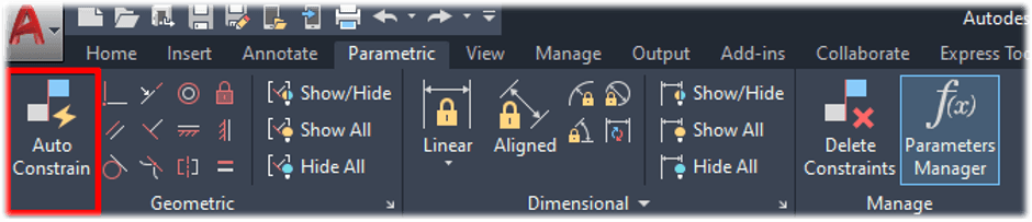
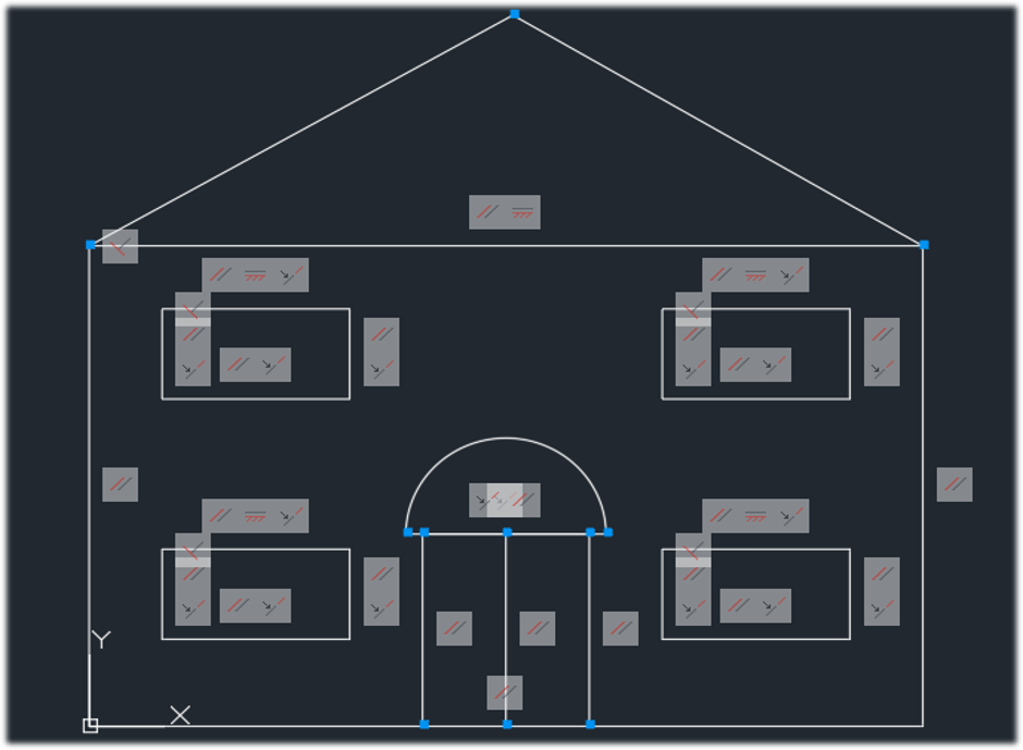
After selecting Auto Constrain command you can select the objects in your model that you want to constrain. After completing the command, all the selected components with constraints applied have icons next to them showing what constraint is applied to each component.
In the image below, I have zoomed in to one of the windows. You can see that I have highlighted the parallel constraint icon on the left side vertical line which automatically highlights the right side vertical line and parallel icon to show that this is the related object and constraint.
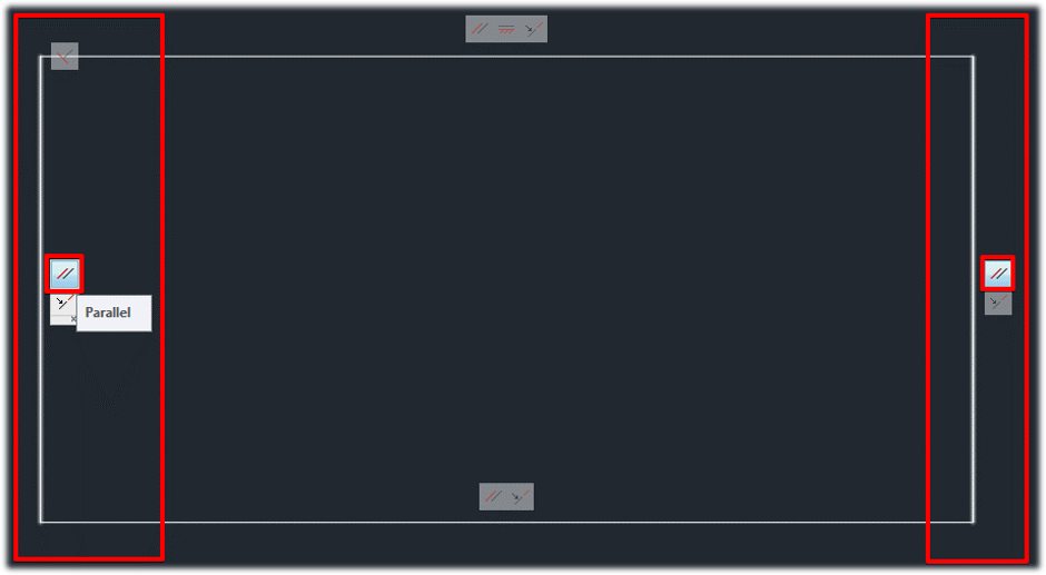
These two lines will remain parallel to each other if the constraint remains. To remove a constraint right click on the icon and select delete.
Now that my model is fully constrained, I will add some parameter to control the size of the model. Choose the parameters you want to apply, click on points on the model that you wish to apply the parameter to and finally choose names for your parameters such as ‘Width’ or ‘Height’.
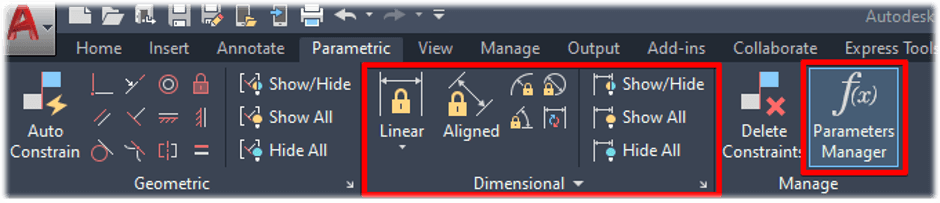
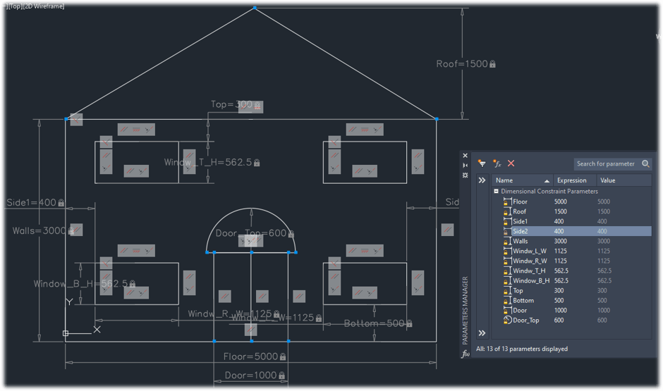
Now I have a list of parameters in my ‘Parameter Manager’ which displays the parameter expression and value, this means I can control the size of my model by adjusting the Expression in the Parameter Manager.
I can also swap out dimensions in the expression and replace them with a formula using the parameter names in the formula.
The example below shows that all my dimension parameters are driven by the size of the ‘Floor’ parameter.
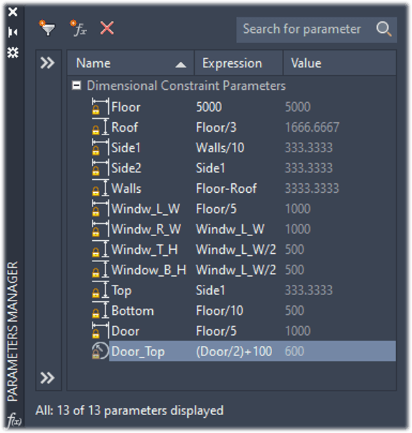
When I adjust the size of the floor parameter, the entire model updates.
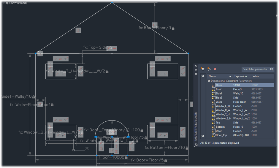
There are many different applications where this can be very useful and save a lot of drafting time using just one or two dimensions to completely change your entire drawing at the click of a button.
For more information on this blog post or if you have any other questions/requirements, please complete the below form:
Related Links
AutoCAD Software – Purchase Online | Man and Machine
AutoCAD Training Courses – Autodesk Authorised | Man and Machine
AutoCAD Essentials Training – Online Booking | Man and Machine
Autodesk AEC Collection – Platinum Partners | Man and Machine