In this blog I am going to detail the correct procedure for creating a symbol to use in AutoCAD Electrical.
AutoCAD Electrical uses blocks with attributes for its symbols. These attributes determine what type of symbol the block is, which in turn determines the behaviour of the block. Below is an example of a relay coil symbol open in the AutoCAD Block Editor.
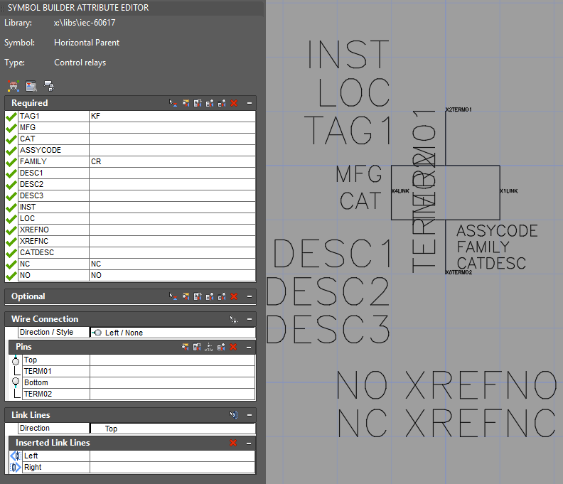
All the text entities in this image are attributes, they have a Tag, Prompt and Value associated to them. In the block editor you see the Tag, in a normal drawing you will see the Value.
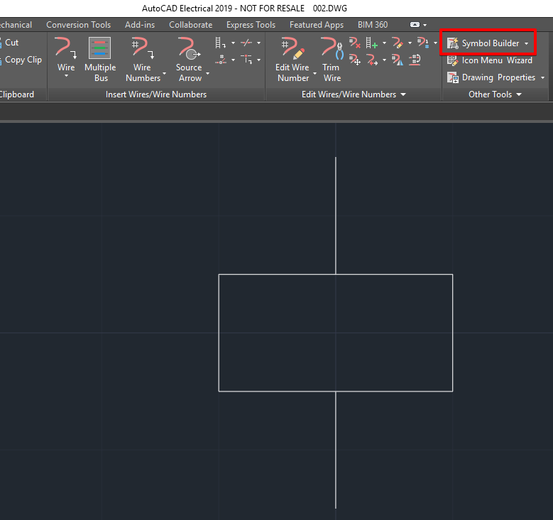
To create this block, first you need to draw the required geometry and select the ‘Symbol Builder’ icon.
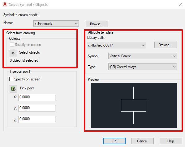
In the next box you decide what type of symbol it is.
Once open in the Block Editor, on the left hand side you can see the ‘Symbol Builder Attribute Editor’. This panel allows you to place ‘Required’ and ‘Optional’ attributes, you can also place ‘Wire’ connections and ‘Link’ connections.
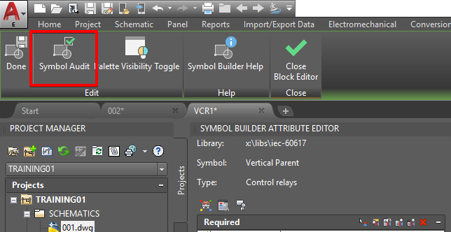
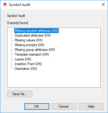
Once all the required attributes and connections have been placed, it is important to carry out a symbol audit to ensure that the symbol will work.
Once audited you then need to save your symbol into your custom symbol library using the correct coding.
The first letter of the filename will be either V or H, for Vertical or Horizontal, for example if the symbol is designed to fit on a vertical wire line the first letter of the symbol filename should be ‘V’.
The next couple of letters will denominate what family the symbol is part of, for example if the symbol is a control relay the next two letters will be ‘CR’. You can find the family codes here.
The next number will be either 1 or 2, 1 is a for a parent symbol such as a relay coil, 2 is for a child symbol such as a relay contact.
If you add another number (not required on all symbols), again either 1 or 2, this will decide whether the symbol is Normally Open or Normally Closed respectively.
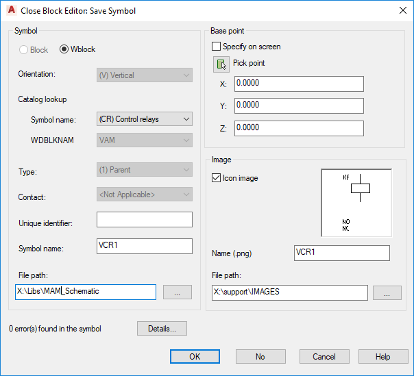
Always ensure that the Base Point is in a logical place!!
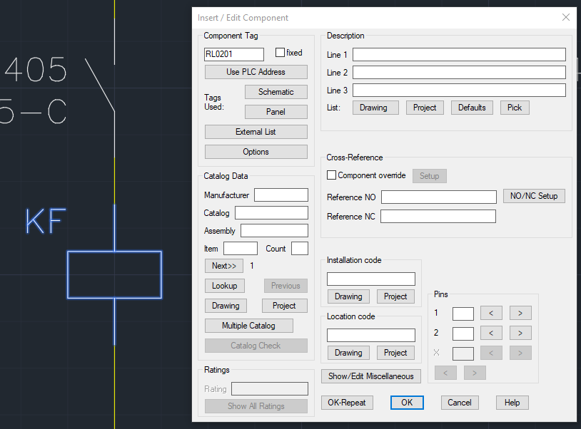
Select the option to place the symbol once complete to carry out a final test on the symbol.
You can use this symbol on any project and share it with your colleagues on a shared network drive.
I hope this helps, please feel free to contact Man and Machine if you have any questions.
For more information on this blog post or if you have any other questions/requirements, please complete the below form:
Related Links
AutoCAD Software – Purchase Online | Man and Machine
AutoCAD Electrical Training – Approved Tutors | Man and Machine
AutoCAD Training Courses – Autodesk Authorised | Man and Machine