Have you ever been using Inventor CAM or Fusion 360’s Manufacturing workspace and wanted a tool that matched what you had in the workshop, or wanted to test a tool before adding it to your library? You can create new tools and libraries quickly within both programs, which can save you time and neaten your libraries up.
Getting to the tool creator within Inventor CAM and Fusion 360 is slightly different but once you are there, the process of creating a new tool is very much the same.
Inventor CAM
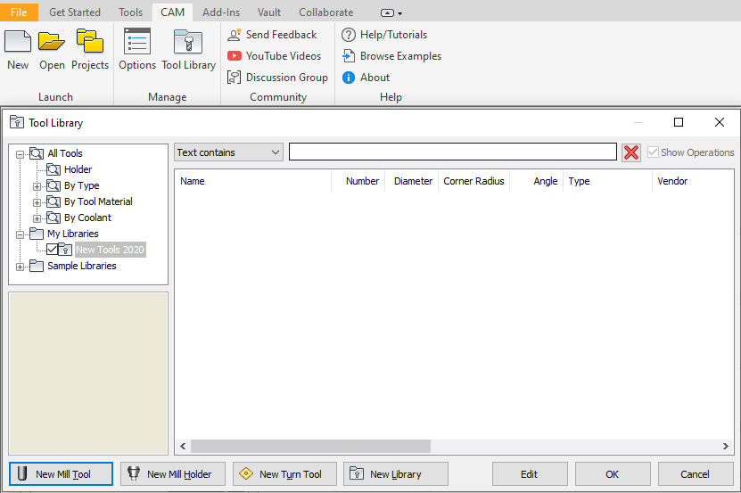
You will need to have the Inventor CAM Add on installed, which is included in the Product Design and Manufacturing collection. Then within Inventor, open the CAM tab in the ribbon, select Tool library, right click on My Libraries and Create New Library, or if you want to add the tool to an existing library you can just open one. Once in the Library you have the option to create New Mill Tool.
Fusion 360
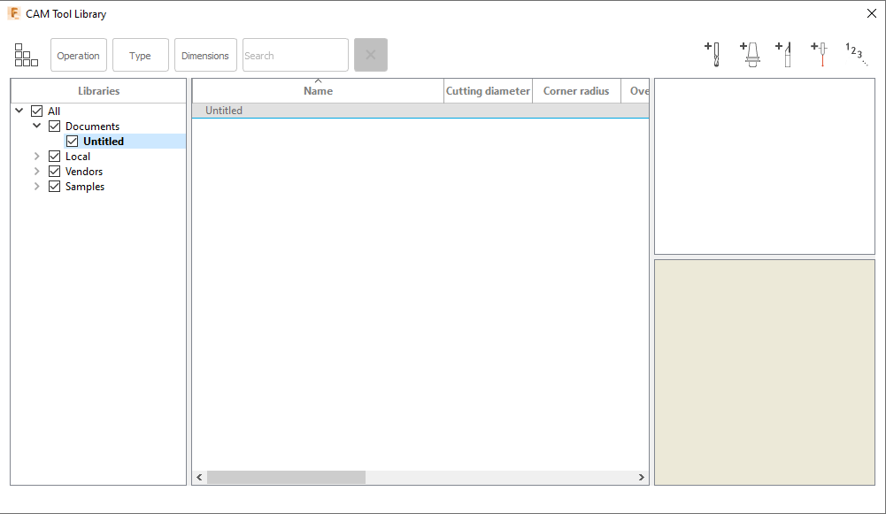
Within the Manufacture workspace in Fusion 360, click on the Tools Icon in the Manage ribbon, this will take you to the Tool Library, simply click on the library you want to edit, or create a new library, then click on tool icon with the + icon next to it.

Creating a Tool
Once you are in the tool creation dialog box you are given the following tabs: General (Fusion also gives Post Processor), Cutter, Shaft, Holder, Holder Geometry (included in Holder for Fusion), and Feed & Speed.
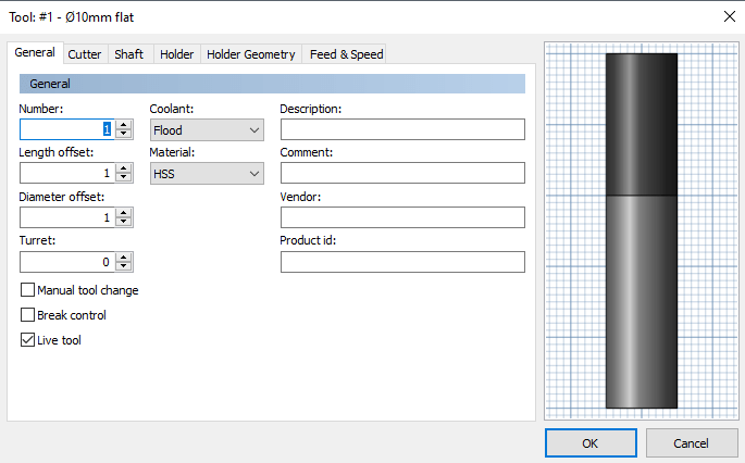
General
In this tab you can enter the tool description, add comments, a vendor or product ID. Though these don’t necessarily adjust the way you use the tool, it adds to the customization of the tools, especially for tool manufacturers, who can send this off to clients to ensure they have the correct dimensions and tools set up.
In Inventor it also gives you the following inputs:
Number gives the option to add a number that the CNC machine will identify the tool by.
Length Offset is normally set when using tools with multiple tips indexed.
Diameter Offset is the index of the tool diameter offset.
Turret
Coolant allows you to choose between Flood, Mist, Through Tool, Air, Air Through Tool, Suction, Flood and Mist, Flood and Through tool, or Disabled.
Material gives you the option between HSS, Ti Coated, Carbide, Ceramics or unspecified.
Manual Tool Change enables you to force a manual tool change on machines that use an automatic tool changer.
Break Control pushes additional information to the final NC code that checks for tool breakage after use.
Live Tool is used for lathes to tell if the tool is live or static in the turret.
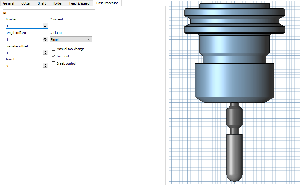
In Fusion 360 these are found under the Post Processor tab
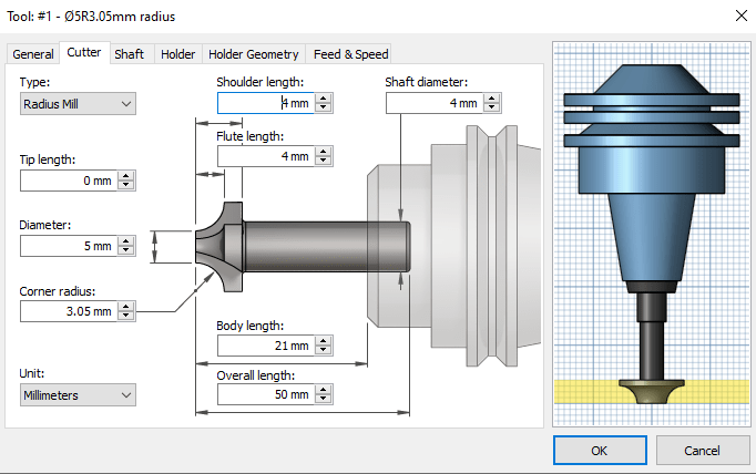
Cutter
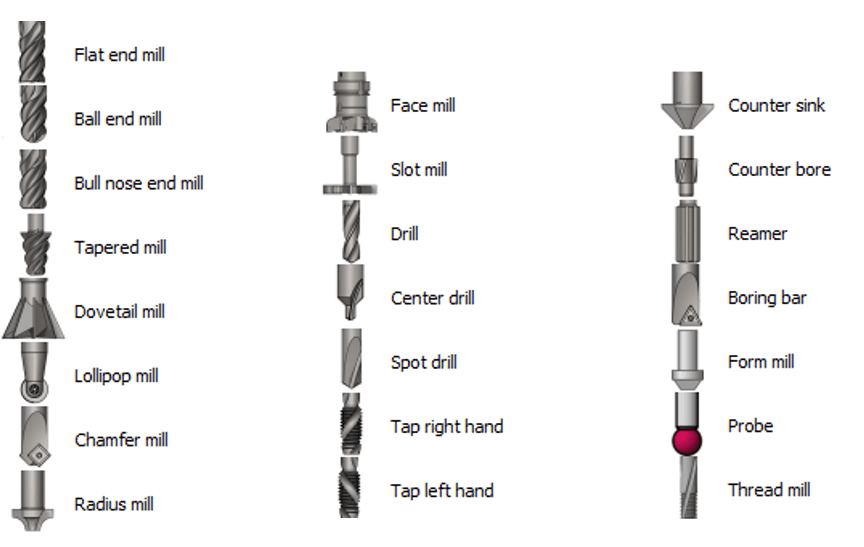
This tab allows you to set up the actual cutter which will take into consideration the shape of the tool under the Type, and the various dimensions under the other options which change based on the type you choose.
The following tool types are available:
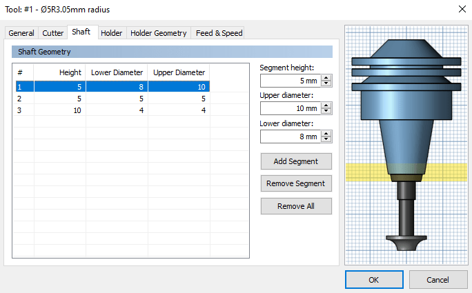
Shaft
If you are wanting to adjust the shaft in any way you can add segments to the Shaft tab, and make the relevant adjustments to the diameters and lengths of the segments, you can have multiple segments which adds to the customization. If your shaft is narrower than the tool itself, it will allow your tool to extend under an edge while machining.
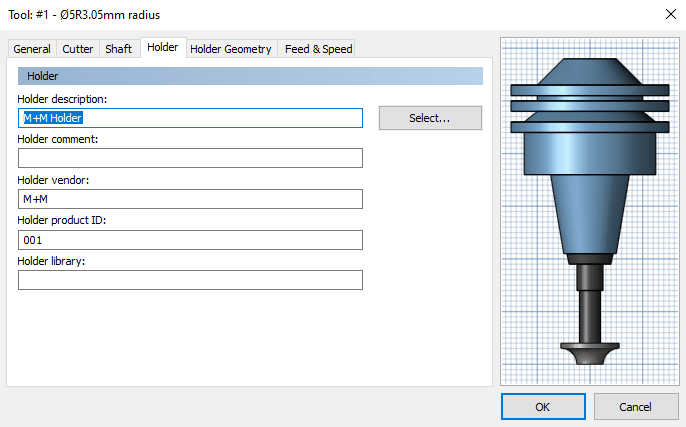
Holder
You can add a holder for the tool based on predefined holders, or you can create your own one for the tool.
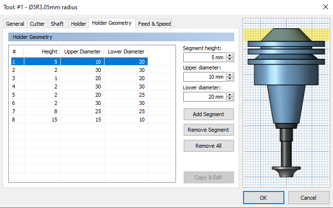
Holder Geometry
You are able to adjust this in the same way as the Shaft by adding segments and adjusting the Upper an Lower Diameter.
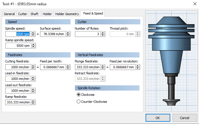
Feed & Speed
Gives you the option of adjusting the Feed and Speed rates during specific functions, this is very important for most tools in order to limit damage and ensure the proper usage of the tools.
You can set the Speed at which the spindle rotates, which can also be given a Ramp Speed.
Setting the Feedrates will adjust the speed at which the tool moves along the surface during Cutting, Lead-In, Lead-out, or Ramping. You can also set Vertical Feedrates which limit the vertical movement in Retracting and Plunging.
And the final option you have is the Spindle Rotation, whether you want your spindle to rotate Clockwise or Anti-Clockwise, this will change orientation of the toolpaths.
As you can see there are a lot of options available to you for customising milling tools within both Inventor and Fusion 360. These make it easy for anyone to create their own tools and even experiment with different setups until you find the right configuration for the job.
For more information on this blog post or if you have any other questions/requirements, please complete the below form:
Related Links
Autodesk Inventor – Autodesk Platinum Partner | Man and Machine
Autodesk Inventor Training Courses | Man and Machine
Inventor Training – Solid Modelling Introduction | Man and Machine
Autodesk Product Design & Manufacturing | Man and Machine
Fusion Training – Autodesk Authorised Trainers | Man and Machine