Generative design has been part of Fusion 360 since 2018, and has quickly become a much loved and used part of the software. From designing bridges and wheels, to chairs and rigs. Generative design has and will continue to push the limits of design and engineering not only in engineering firms but also at home with hobbyists.
In this series I am going to take you through the in’s and out’s of creating a generative designed object in Fusion 360, and will teach you some of the things I have learnt through trial and error.
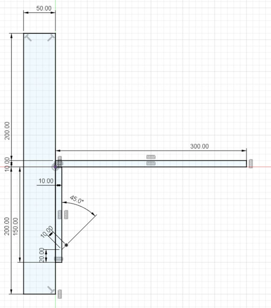
We are going to make an arm for a shelf, and as with most projects in Fusion we start in the Design workspace.
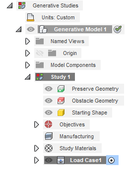
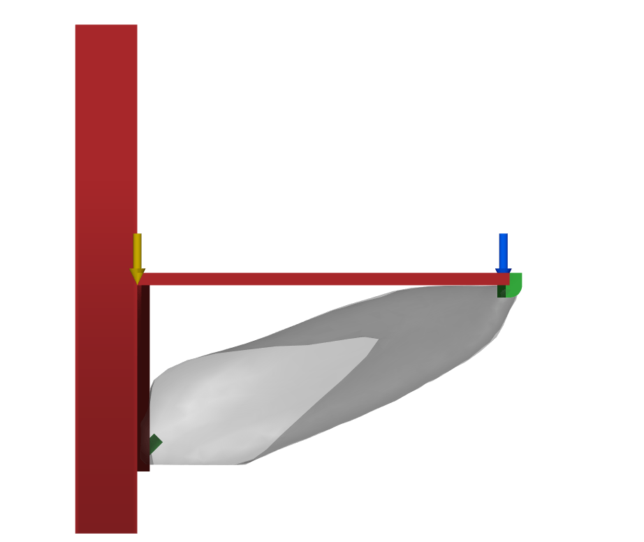
In order for Fusion to generate an object for us, it will need to have at least two points, one of which will need to be fixed in place, and the other will need a load applied to it. This will feed it the data that it needs to generate the connection between the two points. These two (or more) objects are the Preserve Geometry, and they will be highlighted in the Generative Design workspace in green.
You can also include Obstacle Geometry, these are Red in the Generative Design workspace and is a region that will be avoided when creating your Generative Designed object. These are important for adding holes for bolts, wires, hands, and areas where things need to move.

For our design I have made simple 2-Point rectangles to represent the Wall, Shelf, and Mounting Bracket (which will support the shelf on the wall) as Obstacle Geometry. For the Preserve Geometry I have created Two L Shape Extrusions to hold the shelf up, and one Peg that will go into the Mounting bracket.

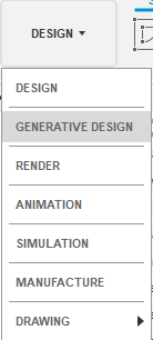
Once you have created the geometry you are wanting to add to your study, you can change your workspace to Generative Design by clicking on the Design button in the top right.

Within this workspace we are given different options which will help us set up our test. Fusion have designed this to work from left to right, so as long as you stop by each button on your way to the generation you should have all your bases covered.
The first thing we will notice is that there is already a study in the tree, so there is no need to create one using the Study button. We can name the Study by double clicking its name, for this one I will call it Basic Study, as we will add more a little later.
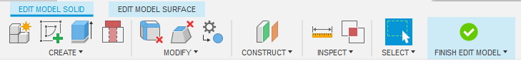
The Next option we have is to Edit Model, we will skip this one for now as our model is exactly as we need it, but this is useful for adding obstruction geometry and removing faces and features.
We then move onto Design Space, where we will add the Preserve and Obstacle Geometry, it is as simple as selecting either option then clicking on the components you would like to put in each category. They will then turn into their respective colours and be added to the Browser. If you have any objects that are hidden, you can turn the visibility of each of geometry categories off so that they all disappear as you select the objects until everything has been selected.
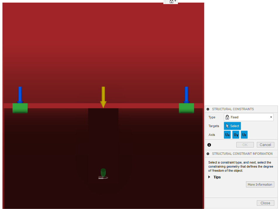
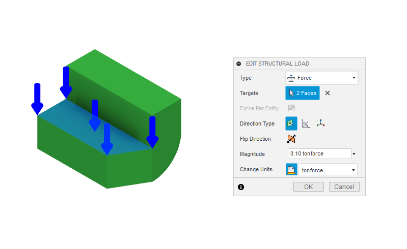
Now that you have your Preserve and Obstacle Geometry set up, you will need to load and constrain it. For this study I have added a Fixed Constraint to the Peg where it meets the Wall Mount.
For the Load I have added a load of .1 Ton to each of the L-Shaped Extrusions where the shelf will rest. Note that there is also a gravitational load that is automatically applied in the Z- direction this can be deleted.
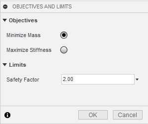
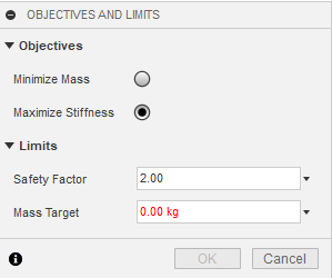
Once you have Constrained and Loaded your components, we need to set an Objective for the study, for this we have two options, Minimize Mass, or Maximize Stiffness.
Minimize Mass will start with a big block connecting the points, then remove as much as it can until you are left with as little mass as possible for the conditions set.
Maximise Stiffness will require a Mass Target and build up the stiffness of the object until it reaches the required Mass.
Both options allow you to put in a safety factor.
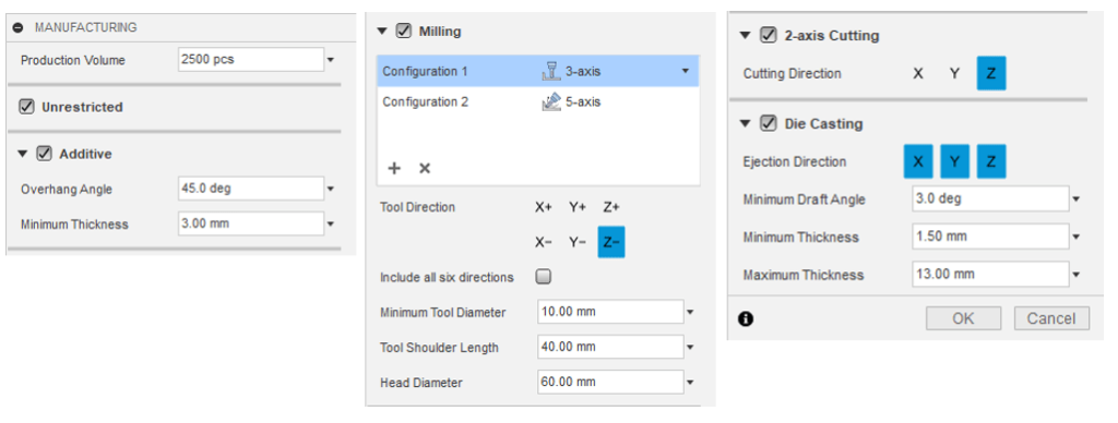
Within the Manufacturing options you can include Unrestrictive, Additive, Milling (5-, 3-, 2.5- and 2- Axis) and Die casting. I recommend selecting all of them for a study unless there is a specific one that you are needing to use, as it will be included in a new study and may create a different shape to one you would get by selecting only one Manufacturing method
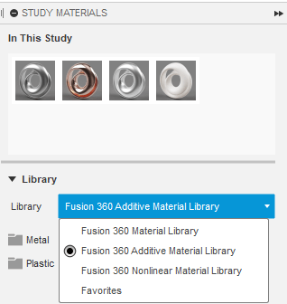
Lastly, we need to choose the Materials that we will add to the study, again I would suggest adding as many reasonable materials as possible, there is a limit of 5 materials per study. For this basic study I have selected Aluminium, Copper, Rilsan Invent Natural, and Stainless Steel.
The study will now take into account the strengths and manufacturability of each material and add it to the part generation.
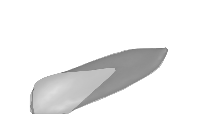
All that is left is to test our setup with the Previewer, this will give you any warnings and show you an estimation of the final result. We will expand on the final results in the next blog.
For more information on this blog post or if you have any other questions/requirements, please complete the below form:
Related Links
Fusion 360 | Man and Machine
Fusion Training – Autodesk Authorised Trainers | Man and Machine