Using parametrics in Inventor to define your model can not only save you time and money down the track, but also open up new pathways to design optimisation and configuration. If you are not yet using parameters and would like to see how they can be better leveraged, read on.
What are parameters?
When we are defining our model in 3D CAD, we can use various types of values. These values can be numbers, text or even Boolean statements like ‘True’ or ‘False’. From such humble beginnings, we can define any number of things that make up our model, including the:
– Length of a line in a sketch
– Extent of extrusion
– Angle of a revolution
– Number of members and the spacing of a pattern
– Material or colour of a part
– The angle of an angular constraint in an assembly
Traditionally, we have assigned static values to these – numbers, texts or Booleans that never change. But what happens if, say, we want to change the width of our box, or the length of our beam? With static values, we’d be forced to go into the sketch and extrusion respectively, and manually change the value. The time and error potential of this rework increases proportionally with model complexity. What happens if we need to ensure one value is double another at all times? Failure to update the dependent value could result in an erroneous design; catastrophe! Enter parametrics to save the day.
Parameters are simply alterable values that we can define our model in place of static values. These parameters are assigned a value, and that value is used wherever the parameter is called upon. Consider the following: if we have a parameter “LENGTH = 3000”, and we were defining the length of a beam extrusion using the parameter “Length”, the beam would be 3000mm long. If the parameter LENGTH were later changed to 4000, the beam would become 4000mm long. Additionally, any other parameters calling on LENGTH would change accordingly.
When can we use parameters?
Wherever we can assign static values, we can instead assign parameters.
Preserving Design Intent
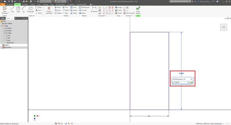
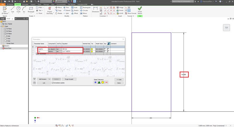
One of the advantages of using parameters is that we are able to preserve design intent easily. Consider the following: a box whose depth must always be double its width. When first creating the box, we may design its width to be 225mm, in which case we would define its depth to be 450mm. However, if we were to later change this width to 300mm, its depth would not automatically change to 600mm. If we forgot to change its value the design intent would be lost.
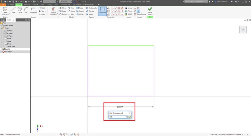
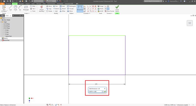
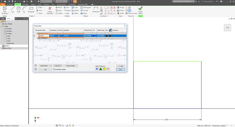
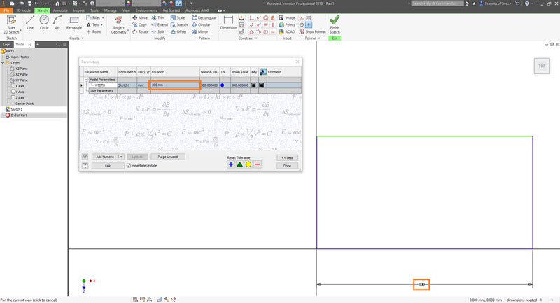
Now let’s consider the same situation but instead using parameters. We begin by defining the width as “WIDTH = 225mm”. This creates the model parameter “WIDTH” and assigns it the value “225mm”. It also defined the width of the box as “WIDTH”. Next, we can define the depth of the box as “= WIDTH*2”. Now, whenever the parameter “WIDTH” is changed, both the width and the depth of the box are changed appropriately. Design intent is preserved and the day is saved!
The next level: iLogic and Configurators
Having control of parameters is fantastic, but sometimes you need a greater level of control. Consider the case of a box with a hole in it. Parameters may change the width and depth of the box, but the hole-size is to be maintained. There would be a critical value for WIDTH and DEPTH below which the hole will start to cut into the walls of the box; this may be undesirable. In Inventor, we are able to get around this issue by disabling the hole using a bit of iLogic (model-embedded code that responds to and manipulates parameters). Our logic may say that if WIDTH or DEPTH < 22mm, then hide the hole. If they are >2mm, make the hole appear again. As you can see from such humble beginnings, enormously complex parametric models can be created.
A model which changes itself following inputs from a user in accordance with its parameters and logic is said to be a configurator. If you have ever fantasised about a luxury car (https://www.audi.co.uk/explore-models/audi-car-configurator.html) you may have come across one already. Configurators such as these are easily created in Inventor simply using parametrics and iLogic.
Optimisations
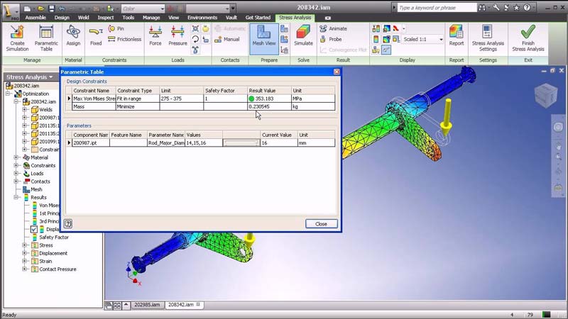
In the world of digital prototyping, the dream is to run analyses on a number of design variants and choose the one best suited. This is easily achievable using parametrics. Consider a drive shaft which must be optimised for diameter – If the diameter is too small, it will break upon transmitting power; however, if it is too large, it will be too heavy. A user may simply define the parameter ‘SHAFT_DIAMETER’, and run a series of FEA analyses on the shaft. The analysis is repeated automatically for each diameter of the shaft between 12mm and 16mm at 1mm increments, yielding the ideal shaft diameter to within 1mm. In this way, parametrics can aid in design optimisation.
Conclusions
In many ways, a parametric 3D model is in fact a ‘4D model’ in that it is defined not only in 3 geometric dimensions, but also with respect to changes in parameters. While it may appear intimidating at first, parametrics are very easy to grasp, and an invaluable tool for any designer or engineer.